CLAS OE 3010 Manual - Halaman 10
Jelajahi secara online atau unduh pdf Manual untuk Sensor Keamanan CLAS OE 3010. CLAS OE 3010 12 halaman. Voltage detector

OE 3010
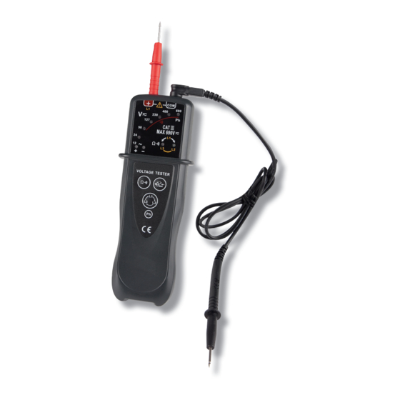
VOLTAGE DETECTOR
Characteristics and range for use:
1. Voltage detection: 12V < U < 69oV
2. Frequency: DC, 50...6oHz +- 5%
3. High impedance does not trigger 3omA differential circuit breaker.
4. Max. peak current at 69oV:
ls < 0.3A/ ls(55) < 3.5mA
5. Response time: instantaneous
Live wire/neutral wire identi cation
1.Connect the red test probe to the " + " jack or connect the black test lead to the " COM " jack.
Warning: To avoid electric shock and lethal personal injury, only one probe should be connected to the tester.
2. Connect the probe to the conductor to be tested and touch one nger to the " Ph " contact area.
3. If the conductor is a live wire's conductor, the Ph " (69oV) LED will ash red and the buzzer will sound beeps.
Characteristics and range for use:
Characteristics and range for use:
1. Détection: U > 127V AC
2. Frequency: 50...60 HZ +/- 5%
Continuity test
Before performing a continuity test, disconnect all power to the circuit to be tested and discharge all capacitors
thoroughly.
1. Connect the red test probe to the " + " jack and the black test lead to the " COM " jack.
2. Connect the two test probes across the circuit to be tested.
3. Press and hold down the continuity test key.
4. If the circuit under test has continuity and its resistance is less than 2OOk , the red continuity indicator LED will
light up and the buzzer will sound continuously.
5. Release the continuity test key to nish the test.
Note: Before test, make sure that there is battery installed in the battery compartment.
Phase Rotation test
Before phase rotation test, verify the presence of voltage on the three phases to be tested on a three-phase system.
1. Connect the red test probe to the " + " jack and the black test lead to the " COM " jack.
2. Connect the red test probe to the rst phase and the black test probe to the second phase.
3. Press the phase rotation test key.
4. If the L1-to-L2 green LED lights up, the phase rotation order is clockwise. If the L1-to-L3 red LED lights up, the
phase rotation order is anticlockwise.
Note: The voltage detection function remains active during this test. Before test, make sure that battery has been
properly installed in the battery compartment.
Characteristics and range for use:
1. Voltage: 360V < U < 690V
2. Frequency: 50Hz – 60Hz (+/- 5%)
