CLAS OE 3010 Manual - Halaman 7
Jelajahi secara online atau unduh pdf Manual untuk Sensor Keamanan CLAS OE 3010. CLAS OE 3010 12 halaman. Voltage detector

OE 3010
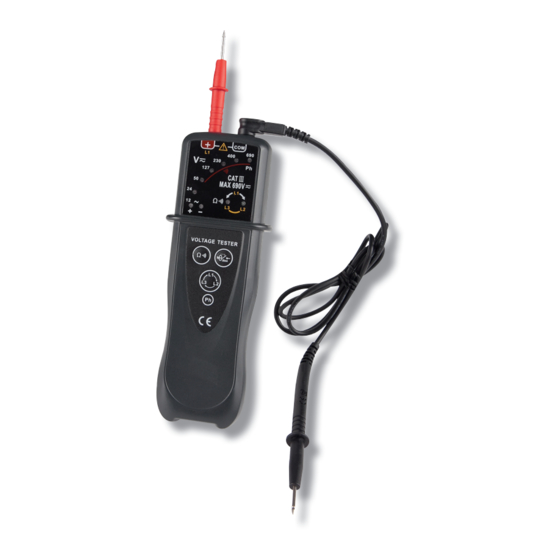
VOLTAGE DETECTOR
STRUCTURE
1. Disconnectable red test probe
2. Disconnectable black test lead with probe
3. LEDs for low voltage, and/or polarity indications
4. Tactile Barrier, protecting the user to prevent any accidental
contact with an naked conductor
5. Continuity test key
6. Phase rotation test key
7. " Ph " contact area
During live wire/neutral wire detection, you should touch this "
Ph " contact area with a nger to improve the tester's detection
sensitivity.
8. RCD test key
9. Green phase-rotation LED: clockwise
10. Red continuity indicator LED/phase-rotation LED:
anticlockwise
11. Dangerous-voltage LED ramp (red LEDs)
CHARACTERISTICS
Power Supply:
9V battery, 6F22 or equivalent, one piece
Buzzer:
Beeps for live wire identi cation. Emits continuous sound for the voltage > 5oV test and continuity
If there is no battery installed in the tester, the buzzer will not sound.
Operation Environment:
-10°C to 55°C, < 75%RH
Storage Environment:
-10°C to 55°C, < 85%RH
Altitude:
2000 meters
Size: 172><64><38mm (mainbody only)
Weight: About 18og (including battery)
