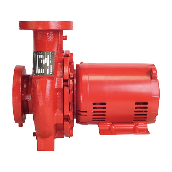
Armstrong 4280 Series Instruksi Kerja Layanan - Halaman 3
Jelajahi secara online atau unduh pdf Instruksi Kerja Layanan untuk Pompa Air Armstrong 4280 Series. Armstrong 4280 Series 4 halaman. Motor mounted pump
Juga untuk Armstrong 4280 Series: Petunjuk Instalasi dan Pengoperasian (4 halaman), Panduan Petunjuk Pemasangan dan Pengoperasian (12 halaman), Panduan Petunjuk Pemasangan dan Pengoperasian (10 halaman)

Note the impeller key and shaft sleeve spacer [ 7 1]. Remove
both for storage.
9 . remove mechanical seal from motor shaft
The mechanical seal spring usually comes free with the impel-
ler. The mechanical seal rotating element [62] must be pried
loose with pry bars or screwdrivers. Once loosened, the seal
may be pulled free of the shaft.
Do not damage the carbon face when removing the rotating
assembly. It may be needed for analysis if seal failure investiga-
tion is required.
10. remove seal seat from adapter
The mechanical seal seat [6 0], usually o ring mounted Ni-
Resist material, is pried loose from the recess in the adapter.
If the seat cannot be removed in this manner, remove the motor
capscrews [4 4] and separate the adapter [40] from the motor
[ 70]. A screwdriver may then be used to push the seat out of
the adapter from the rear.
11. remove old casing gasket
The former casing gasket [ 101] should be scraped from the
casing and adapter, leaving clean surfaces for the new gas-
ket. A standard putty knife and wire brush are useful for this
purpose)
assembly procedures:
12 . replace mechanical seal
Clean the shaft sleeve [ 70] surface, ensuring all the former
seal elastomer pieces have been removed. Inspect for damage.
Replace if necessary. (See separate instructions for removal of
the shaft sleeve [File No. 6 04 2. 25]). Inspect the water slinger
[ 39] and replace if damaged. Install a new seal seat [6 0] in
the adapter cavity, being sure the lapped (polished) side of the
insert is facing up. Ensure that the cavity has been thoroughly
cleaned. Lubricate the seat o ring with a small amount silicon
or glycerine lubricant and press down, straight and even, into
the cavity. Do not press the seat in with bare fingers, use a
clean cloth or the cardboard disc typically supplied with the
seal. Contamination of the polished and lapped seat face could
cause leakage. If the adapter was removed from the motor,
replace now, taking care that the seal seat is carefully guided
over the motor shaft.
Series 4280 Motor
Mounted Pump
Lubricate the inside of the seal rotating assembly [62] with a
small amount of silicon or glycerine lubricant and slide onto
the shaft sleeve [ 70] with a twisting motion, carbon face first,
until the carbon face is pressed firmly against the seal seat
[6 0]. Pressing on the seal rotating assembly metal parts, with
a screw driver, all the way around the seal, will ensure that the
faces are mated properly.
Remove the spring retainer from the seal spring and place the
seal spring over the seal rotating assembly.
13 . replace pump impeller
Install the shaft sleeve spacer [ 7 1] and impeller key on the
shaft and place the seal spring retainer onto the impeller hub
register. Slide the impeller in place on the motor shaft. Take
care and ensure that the seal spring is kept in place on the
seal rotating assembly and fits well into the retainer on the
impeller hub.
14 . tighten impeller capscrew
It is good practice to replace self locking screwa, once removed.
Install the impeller capscrew and washer [86 & 83]. Hold the
impeller the same way as when the capscrew was successfully
loosened (Bar or screw driver placed carefully between the im-
peller blades) and tighten the capscrew with a socket wrench.
15 . install new casing gasket
Insert new casing gasket [ 101] onto the register on the adapter.
16. slide rotating assembly into place
The rotating assembly (Motor, adapter and impeller
combination [ 10, 40 & 8 0]) may now be pushed into place in
the casing.
Once in place, any casing supports should be removed.
17. casing capscrews
The casing capscrews [ 104] are now installed and evenly tight-
ened with a wrench. Tighten the capscrews a little at a time,
diagonally across the casing, to assure even gasket pressure.
18. motor mounting capscrews
The capscrews that hold the pump to the foundation are now
installed and tightened.
19 . isolation valves
Replace the casing drain plug and open the suction and dis-
charge isolation valves.
s e rv i c e wo r k
i n s t r u c t i o n s
3
