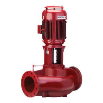
Armstrong 4360 Panduan Petunjuk Pemasangan dan Pengoperasian - Halaman 5
Jelajahi secara online atau unduh pdf Panduan Petunjuk Pemasangan dan Pengoperasian untuk Pompa Air Armstrong 4360. Armstrong 4360 12 halaman. Vertical in-line pump
Juga untuk Armstrong 4360: Panduan Petunjuk Pemasangan dan Pengoperasian (14 halaman)

Internal rusting can be prevented by removing the plugs at
the top and bottom of the casing and drain or air blow out all
water to prevent rust buildup or the possibility of freezing. Be
sure to reinstall the plugs when the unit is made operational.
Rustproofing or packing the casing with moisture absorb-
ing material and covering the flanges is acceptable. When
returning to service be sure to remove the drying agent from
the pump.
uncr ating
Armstrong Vertical In-Line pumps are thoroughly inspected
before shipment to assure they meet with your order require-
ments. After removing the pump from the crate, make sure
the equipment is in good order and that all components are
received as called for on the packing list. Any shortages or
damage should be reported immediately. Use extreme care
in handling the unit, placing slings and hooks carefully so that
stress will not be imposed on the pump. Never Place Cable
Slings Around The Pump Shaft. The eye bolts or lifting lugs
on the motor are intended for lifting only the motor and not
the complete unit.
handling
large vil units
One effective way of lifting a large Series 430 0 unit from the
shipment pallet following uncovering the unit is to place lift-
ing hooks through the motor lifting rings or straps around the
upper part of the motor and carefully lift sufficiently to stand
the pump vertically. Lift only sufficiently to remove the pallet
then lower onto a flat surface. The pump and motor unit will
free-stand on the casing ribs. Remove the coupling guard and
place (2) lifting straps through the pump/motor pedestal,
one on each side of the motor shaft and secure to the lifting
device. With the straps in place, using a spacer bar if neces-
sary to protect the motor fan cover, the whole assembly can
now be lifted securely and placed in position in the piping.
Secure pallet and lift pump vertical using motor eye-bolts lift
only to clear pallet then sit on the flat surface
Series 4300, 4360 and 4380
Vertical in–line pumps
Remove coupling guard and place lifting straps on each side
of coupling, use spacer bar if necessary to protect motor fan
cover.
important:
Do not run the pump for any length of time under
very low flow conditions or with the discharge valve
closed. To do so could cause the water in the casing
to reach super heated steam conditions and will cause
premature failure and could cause serious and dramatic
damage to the pump and surrounding area.
installation
1.
location
• In open systems, locate the unit as close as practical to
the liquid being pumped, with a short, direct suction pipe.
Ensure adequate space is left above and around the unit
for operation, maintenance, service and inspection of
parts.
• In closed systems, where possible, the pumps should be
installed immediately downstream of the expansion tank
/ make-up connection. This is the point of zero pressure
change and is necessary for effective pump operation. Do
not install more than one expansion tank connection into
any closed hydronic system.
• Electric motor driven pumps should not be located in
damp or dusty location without special protection.
• Airflow into the motor and/or motor fan should not be
obstructed.
2.
installation
• When installing vertical in-line pumps, an important
consideration to accrue full added-value from the pump
design is to ensure that the pump is pipe-mounted
and free to 'float' with any movement, expansion and
contraction of the piping. Should any vertical in-line pump
use supports to the structure it is imperative that no pipe
in sta l l a t io n &
op er a ting in struct io n s
5
