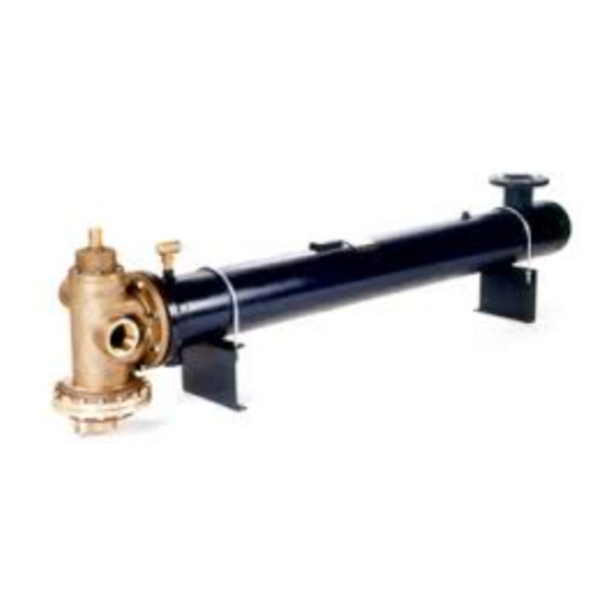
Armstrong FLO-RITE-TEMP 535 Petunjuk Pemasangan dan Penyesuaian - Halaman 4
Jelajahi secara online atau unduh pdf Petunjuk Pemasangan dan Penyesuaian untuk Pemanas Air Armstrong FLO-RITE-TEMP 535. Armstrong FLO-RITE-TEMP 535 17 halaman. Instantaneous water heater. instructions for single and double wall units
Juga untuk Armstrong FLO-RITE-TEMP 535: Petunjuk Pemasangan dan Penyesuaian (20 halaman)

down stream from the thermal loops and prior to
the recirculation loop (if one is used) (See Fig.
3-1B). This allows for quick and easy setting of
the FLO-RITE-TEMP by one person. By isolating
the unit from the hot water system, flow can be
controlled to drain through the globe valve while
monitoring outlet water temperature during low
and high flow adjustments on the water heaters
mixing valve.
Minimum line sizes to drain should be as
follows: model 415 = 3/4", model 535 = 1",
model 665 = 1-1/4", model 8120 = 2". Line
sizes smaller than these will not allow sufficient
flow for making high flow settings on the mixing
valve.
5.
A water temperature gauge should be installed
directly after the by-pass drain valve. This
thermometer is only used for inital temperature
adjustments of the Flo-Rite-Temp or
troubleshooting the unit. (See Fig. 3-1B)
6.
If a recirculation system is used with a
FLO-RITE-TEMP, a small diverting valve must
be piped into the loop return downstream of the
recirculating pump (See Fig. 3-1C). This device is
used to divert recirculated water back to the
heater for reheating if the temperature of the
water drops too low due to no hot water demand
from the system plus piping radiation losses (See
page 9 for operation explanation). Be sure to pipe
See Fig. 3-1E for location of each option within the system. All options would be installed downstream of
the water heater in the outgoing recirculation loop, if one is present, or downstream of the hot water thermal
loop if recirculation is not used but always before the first hot water take off from the system.
Option #1 A temperature relief valve set at roughly 15-30 degrees above that of the FLO-RITE-TEMP
will help prevent any chance of overheated water reaching the faucets. (NOTE: Normally unit will fail closed
and either no water or only cold water will flow from the unit.)
Option #2 A 3-way blending valve with a set
point 10-30 degrees above that of the FLO-RITE-
TEMP will help prevent the chance of overheated
water reaching the faucets in the event of unit failure.
Under normal operating conditions the hot water flows
straight through the blending valve from Port B to Port
A. But in the event of an overheated situation, the
blending valve will open Port C to add sufficient cold
water to maintain a constant temperature . (NOTE:
The blending valve should be sized to handle the
maximum flow of the system).
October 31, 2002 @ 3:15 pm
OPTIONAL SAFETY EQUIPMENT
4
in unions and isolation valves to facilitate diverting
valve removal required when element replacement
is needed. A throttling type valve should be
installed in a full return line size bypass around the
diverting valve in order to balance the flow to the
diverting valve. This is especially needed when
recirculating pumps are large or oversized.
7.
For a recirculated system, a small constant running
pump should be piped in on the return side of the
loop (See Fig.3-1D). This pump should be sized to
move approximately 10% of the maximum rated
gpm of the FLO-RITE-TEMP in the system with
enough head to overcome the head encountered in
the loop.
NOTE: A thermometer should be installed in
the outgoing loop to monitor system temperature
(Fig. 3-1E). A thermometer may also be
installed on the loop return to monitor
temperature drop through the loop or to help
troubleshoot the diverting valve (Fig. 3-1D). The
thermometer referred to in point #4 and Fig. 3-1B
should only be used to set the FLO-RITE-TEMP
and never used to monitor system temperature.
NOTE: Expansion tanks should be used in on/
off demand applications where there is a short
duration of time from high flow to no flow of
water, i.e., a shut off time of 10 seconds or less.
(See Fig. 3-1F)
Temperature
Relief Valve
Option #1
Loop or System
Thermometer
Hot Water from
Flo-Rite-Temp
