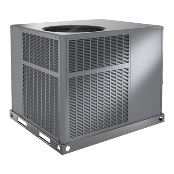
Armstrong Air NP14A Series Panduan Petunjuk Pemasangan dan Pemeliharaan - Halaman 16
Jelajahi secara online atau unduh pdf Panduan Petunjuk Pemasangan dan Pemeliharaan untuk Pendingin Udara Armstrong Air NP14A Series. Armstrong Air NP14A Series 20 halaman. Residential packaged units

System Performance
This equipment is a self-contained, factory optimized
refrigerant system, and should not require adjustments to
system charge when properly installed. If unit performance
is questioned, perform the following checks.
Ensure unit is installed per manufacturer's instructions
and that line voltage and air flow is correct. Refer to
the following tables for proper performance value. The
indoor metering device varies by model; when checking
performance of a unit using an orifice for metering, refer to
the suction superheat value to judge performance. When
checking performance of a unit that uses an expansion
valve for metering, refer to the subcooling value to judge
system performance.
If the measured performance value varies from table value
allowance, check internal seals, service panels and duct
work for air leaks, as well as restrictions and blower speed
settings. If unit performance remains questionable, remove
system charge, evacuate to 500 microns, and weigh in
refrigerant to nameplate charge. It is critical that the exact
charge is re-installed. Failure to comply will compromise
system performance.
If unit performance is still questionable, check for
refrigerant related problems, such as blocked coil or
circuits, malfunctioning metering device or other system
components.
Model
Superheat +/- 3°
2 Ton
2.5 Ton
3 Ton
3.5 Ton
4 Ton
5 Ton
Based on outdoor ambient temperature of 82°F, and indoor
entering air of 80°F db, 67°F wb.
Table 4. Air Conditioner Unit Cooling System
Performance Values
Model
Superheat +/- 3°
2 Ton
2.5 Ton
3 Ton
3.5 Ton
4 Ton
5 Ton
Based on outdoor ambient temperature of 82°F, and indoor
entering air of 80°F db, 67°F wb.
Table 5. Heat Pump Cooling System Performance
Page 16 of 20
Suction
Liquid
Subcooling +/- 2°
13
16
14
14
16
17
Suction
Liquid Subcooling
+/- 2°
18
16
16
22
22
5
Values
Model
2 Ton
2.5 Ton
3 Ton
3.5 Ton
4 Ton
5 Ton
Based on outdoor ambient temperature of 47°F, and indoor
entering air of 70°F db.
Table 6. Heat Pump Heating System Performance
Before performing maintenance operations on the
system, shut off all electrical power to the unit. Turn off
accessory heater power switch if applicable. Electrical
shock could cause personal injury or death.
Periodic inspection and maintenance normally consists of
changing or cleaning the filters and cleaning the evaporator
coil. On occasion, other components may also require
cleaning.
Filters
Filters are not supplied with the unit. Inspect once a month.
Replace disposable or clean permanent type as necessary.
Do not replace permanent type with disposable.
Motors
Indoor and outdoor fan and vent motors are permanently
lubricated and require no maintenance.
Indoor fans are equipped with a permanent magnet
constant torque motor. These motors remain energized and
are controlled by 24V signals. For high static applications,
use Tap 3 for cooling speed and Tap 5 for heating speed.
Evaporator Coil
Dirt and debris should not be allowed to accumulate on
the evaporator coil surface or other parts in the air circuit.
Cleaning should be as often as necessary to keep coil
clean. Use a brush, vacuum cleaner attachment, or other
suitable means. If water is used to clean the coil, be sure
the power to unit is shut off prior to cleaning. Care should
be used when cleaning the coil so that the coil fins are
not damaged.
Do not permit the hot condenser air discharge to be
obstructed by overhanging structures or shrubs.
Issue 2211
Liquid Subcooling +/- 2°
25
15
28
20
35
28
Values
Maintenance
WARNING
507296G03 / 31-5000670
