Distech Controls RS485 UUKL Panduan Instalasi - Halaman 2
Jelajahi secara online atau unduh pdf Panduan Instalasi untuk Unit Kontrol Distech Controls RS485 UUKL. Distech Controls RS485 UUKL 4 halaman. Option module
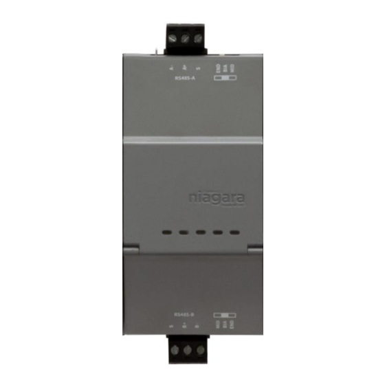
Figure 2: Dual RS485 UUKL Option module
This document covers the mounting and wiring of a Dual RS485 UUKL
option module for an EC-BOS-8 UUKL.
1
RS485-A port COMn (next available). For example, COM3
2
RS485-B port COMn+1 (next + 1). For example, COM4
Precautions
General Precautions
The following are warnings relating to the installation of the EC-BOS-8
UUKL option module.
•
Remove all power to the EC-BOS-8 UUKL before
attaching (plug in) or detaching (unplug) any option
module, to prevent possible equipment damage.
•
Removal of the EC-BOS-8 UUKL's cover is not
required. No configurable or user-serviceable items
(such as jumpers or a battery) are inside the option
module.
Static Discharge Precautions
Static charges produce voltages high enough to damage electronic
components. The microprocessors and associated circuitry within the
devices are sensitive to static discharge.
•
Work in a static-free area.
•
Discharge
any
accumulated. Discharge static electricity by touching a
known, securely grounded object.
Mounting
Mounting the EC-BOS-8 UUKL and all option modules on a 35mm wide
DIN rail is recommended. Mounting on a DIN rail ensures accurate
alignment of connectors between all modules. Tabs on the EC-BOS-8
UUKL or module can be used for panel mounting as an alternate to DIN
rail mounting.
•
Remove all power to the EC-BOS-8 UUKL before
installing
or
"Precautions," page 2.
2/4
static
electricity
you
may
removing
option
modules.
Mounting on DIN Rail
Prerequisite: The EC-BOS-8 UUKL is securely mounted on a 35mm DIN
rail, with adequate room left to mount the module.
1. Pull the option module's locking clip down.
2. Tilt the module to hook over the DIN rail.
3. Push down and in on the unit, fastening to the rail.
4. Slide the module firmly into the EC-BOS-8 UUKL's connector (or
existing option module) to seat.
Repeat for other modules as needed (4 maximum).
5. Push up the locking clip on all modules.
have
6.
Carefully secure both ends of the final assembly with DIN rail end-
clips provided by the DIN rail vendor.
To remove a unit from the DIN rail, pull down its locking clip.
Slide the unit away from other devices, then swing the
bottom out and lift away from the rail.
See