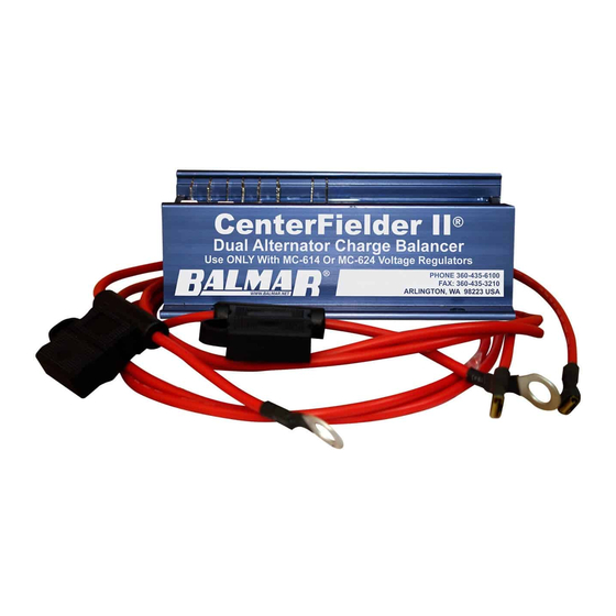
Balmar Centerfielder II Panduan Instalasi dan Pengoperasian - Halaman 4
Jelajahi secara online atau unduh pdf Panduan Instalasi dan Pengoperasian untuk Pengisi Daya Baterai Balmar Centerfielder II. Balmar Centerfielder II 6 halaman. Dual alternator charge balancer
Juga untuk Balmar Centerfielder II: Panduan Instalasi dan Pengoperasian (8 halaman)

7. PORT REGULATOR DASH LAMP TERMINAL-
terminal via a user supplied 16-gauge wire. Female 1/4" spade terminals are supplied for connecting to Terminal #6.
8. PORT DASH LAMP TERMINAL-
1/4" spade terminals are supplied for connection to Terminal #7.
9. GROUND TERMINAL -
is supplied for connection to Terminal #9. Termination to system ground will require a user-supplied spade or ring terminal
connector, depending on the ground location chosen. ALL GROUND CONNECTIONS MUST BE COMMON.
10. STARBOARD "DASH LAMP" LED (GREEN)-
terminal. Activation of the Dash Lamp may occur as a result of high or low voltage, high alternator or high battery
temperature. If LED is illuminated, inspect the starboard voltage regulator long display for advisory codes.
11. STARBOARD REGULATOR DASH LAMP TERMINAL-
dash lamp terminal via a user supplied 16-gauge wire. Female 1/4" spade terminals are supplied for connection to Terminal
#11.
12. STARBOARD DASH LAMP TERMINAL-
16-gauge wire. Female 1/4" spade terminals are supplied for connection to Terminal #12, and for connection to the
starboard regulator's dash lamp.
13. COMMUNICATION PORT-
14. COMMUNICATION PORT-
15. COMMUNICATION PORT-
16. STARBOARD IGNITION INPUT-
switch. Terminal #16 must see zero volts when the starboard engine is turned off, and battery voltage when the starboard
engine is running. BROWN 14-Gauge user-supplied wire is recommended. A female 1/4" spade terminal is supplied for
connection to Terminal #16.
17. STARBOARD REGULATOR IGNITION-
wire. A BROWN ignition wire. A BROWN 14-Gauge user-supplied wire is recommended. A female 1/4" spade terminal is
supplied for connection to Terminal #17.
18. STARBOARD "IGNITION ACTIVATED" LED (GREEN)-
wire. If LED is illuminated, but the starboard voltage regulator is inactive, check for voltage at the regulator's ignition
terminal.
19. STARBOARD ALTERNATOR FIELD OUTPUT TERMINAL (MASTER)-
alternator's field input terminal via a user supplied 12-Gauge BLUE wire. A female 1/4" spade terminal is supplied for
connection to Terminal #19. Alternator-side termination will require a user-supplied spade or ring terminal connector,
depending on the alternator configuration.
20. STARBOARD REGULATOR FIELD INPUT TERMINAL (MASTER)-
regulator's Field Output terminal via a user-supplied 12-Gauge BLUE wire. A female 1/4" spade terminal is supplied for
connection to Terminal #20. The 12-Gauge BLUE wire will replace the regulator's 14-Gauge field wire.
21. "COMBINE" LED (AMBER)-
12/24 will continue to supply balanced field current to both port and starboard alternators when the LED is activated.
Connect Terminal #7 to the port dash lamp via a user supplied 16-gauge wire. Female
Connect Terminal #9 to system ground via 14-gauge BLACK wire. A female 1/4" spade terminal
Connect Terminal #12 to the starboard dash lamp via a user supplied
Factory use only.
Factory use only.
Factory use only.
Connect Terminal #16 to the starboard ignition switch or starboard engine oil pressure
Connect Terminal #17 to the starboard voltage regulator's BROWN ignition
Indicates activation of port and starboard alternators and voltage regulators. The CFII -
Connect Terminal #6 to the port voltage regulator's dash lamp
Indicates activation of starboard voltage regulator's Dash Lamp
Connect Terminal #11 to the starboard voltage regulator's
Indicates activation of starboard voltage regulator's ignition
Connect Terminal #20 to starboard voltage
4
Connect Terminal #19 to the starboard
