esera automation ECO 10 Panduan Pengguna - Halaman 5
Jelajahi secara online atau unduh pdf Panduan Pengguna untuk Pengontrol esera automation ECO 10. esera automation ECO 10 13 halaman. 1-wire controller

Art. No. 11601-24
8
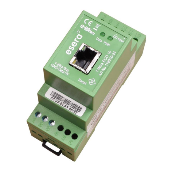
Connection diagram
Module top side, 1-Wire Bus
1 = ground / GND 1-Wire
2 = 1-Wire Data
3 = 5V output
Module bottom side, power supply
11 = Minus supply voltage
12 = Plus supply voltage
5 = Reset Button on the inside
9
Reset Button
Operating the reset button with non-conductive
material, e.g. match.
The reset is carried out via the reset button of the
system.
carried out. When the button is pressed, the unit is
restarted. The stored data is retained, but
all connections are interrupted
This keystroke does not correspond to an
interruption of the power supply.
Note
The Minus pole of the supply voltage / power supply unit of the ECO 10 should be connected to earth
potential (PE). This establishes a functional earth
Note
The module may only be operated at the voltages and under the ambient conditions specified for it. The
operating position of the unit is arbitrary.
The modules may only be put into operation by a qualified electrician.
For further information on the operating conditions, see the following instructions under "Operating
conditions".
* if the sensor or actuator supports Auto-E-Connect. For details, please refer to the operating instructions of the sensor or actuator.
All rights reserved. Reproduction as well as electronic duplication of this user guide, complete or in part, requires the written consent of
ESERA GmbH. Errors and technical modification subject to change. ESERA GmbH 2021
www.esera.de
11601-24 V1.0 R1.1 Manual
Page 5 of 13
