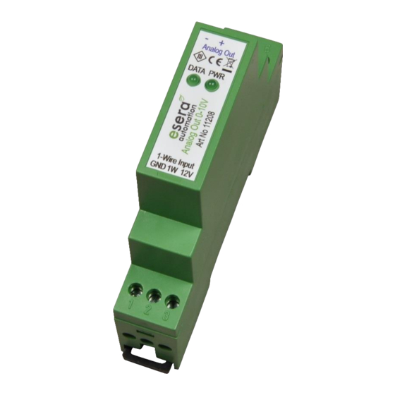
esera automation 11208 Panduan Pengguna - Halaman 5
Jelajahi secara online atau unduh pdf Panduan Pengguna untuk Sistem I/O esera automation 11208. esera automation 11208 7 halaman. Analog output 0-10vdc for 1-wire bus system

Art. No. 11208
10
Software / Control
The Analog Output 0-10VDC works with a 1-Wire interface of type DS2408 (8-fold I/O device), which is controlled
with the 1-Wire commands typical for this device.
The DS2408 device can display a total of max. 256 states through its 8 outputs, which can be read in internally by
a microcontroller and converted into an analog output signal.
The individual DS2408 outputs have the following values: channel 0 = 1, channel 1 = 2, channel 2 = 4, channel 3
= 8, channel 4 = 16, channel 5 = 32, etc. The outputs are read by a microcontroller and output as analog values.
All 8 outputs to value 0 mean 10V output voltage. All 8 outputs to value 1 (or 255 decimal) mean 0V output
voltage.
This logic is inverted. The active outputs are added according to their value and output as analog values. Details
can be found in our example program in the download area of the shop.
Note:
The Analog Output 0-10VDC module starts after switching on the supply voltage into the standby mode, in which
no voltage (0V) is output. In standby mode the DATA LED flashes.
The module changes to normal operation after a voltage value of less than 10V has been output once. In normal
operation a voltage between 0-10V can be output.
11
Control by 1-Wire Controller / 1-Wire Gateway
The 1-Wire interface of the Analog Output 0-10VDC is controlled by standard commands for the device DS2408.
The Analog Output 0-10VDC can easily be controlled via a 1-Wire Controller / 1-Wire Gateway. The following
command is available for this purpose.
11.1
Set analog output
Use the following command to set a new analog value.
Command
SET,OWD,OUTA,OWD-number, output voltage
Example: SET,OWD,OUTA,1,1000
11.2
Data output 1-Wire controller / 1-Wire gateway
For the 1-Wire Analog Output module 0-10V, the following data are output for the status of the analog value.
The following formatting is available since firmware 1.18_43.
data output
1_OWD1|1000
Further information in regards to options and commands can be found in the current 1-Wire Controller /1-Wire
Gateway documentation.
12
Operating conditions
The device may only be operated at the specified voltages and ambient conditions. The device may only be
used in dry indoor areas.
If condensation forms inside the unit, allow at least 2 hours for the unit to acclimatize. Do not operate the
module in an environment in which flammable gases, vapors or dusts are present or could be present. The
building group can be operated only under the supervision of an electrically skilled person.
In industrial facilities, the accident prevention regulations of the federation of industrial professional
associations for electrical installations and equipment must be observed.
13
Assembly
The location of the assembly must be protected against humidity. The device may be used only in dry inside
spaces. The device is designed to be assembled as a fixed device within a switchboard.
.
All rights reserved. Reproduction as well as electronic duplication of this user guide, complete or in part, requires the written consent of
ESERA GmbH. Errors and technical modification subject to change. ESERA GmbH, ESERA-Automation 2020
www.esera.de
=> OWD1,10,00V
=> Controller No._device No._data record | analog value, example 1000 = 10,00V
11208 V2.0 R1.0 Manual
Page 5 of 7
