Camlogic PFG05X Panduan Penggunaan dan Perawatan - Halaman 3
Jelajahi secara online atau unduh pdf Panduan Penggunaan dan Perawatan untuk Alat Ukur Camlogic PFG05X. Camlogic PFG05X 4 halaman. Rotary level indicator
Juga untuk Camlogic PFG05X: Panduan Penggunaan dan Perawatan (4 halaman)
115/230 AC
1
Neutral
2
115V (50/60Hz)
3
230V (50/60Hz)
4
5
Common (max. 10A/250V)
6
SAFETY WARNINGS
The installation, maintenance and diagnostics of the device must be carried out only by authorized personnel informed about the
regulations in force. Before starting work, specialized personnel must have read and understood the instructions. When using
electrically operated equipment, it is necessary to take the appropriate safety precautions, required by current regulations, to
reduce the risk of fire, electric shock, and injury to people.
Before installing the device, check its perfect integrity making sure that it has not been damaged during transport.
The removal/replacement/modification of any part of the device entails the loss of validity of the certifications of the products itself.
The earthing connection is mandatory and the sole responsibility of the installer.
Level indicators must be used within the range of ambient temperatures indicated on the plate. The PFG*...BL models are
suitable for use in low temperatures un to -40°C, thanks to the internal self-regulating heater, which guarantees a service
temperature inside the casing, necessary to its proper operation. When an internal temperature of 20°C is reached, the heater
switches off autonomously.
SPECIFIC CONDITION FOR USE OF ATEX
In accordance with Directive 1992/92/EC / DSEAR 2002, it
is responsibility of the user to ensure that the equipment,
used in areas where an explosive atmosphere might be
present, is maitained in such a way as to reduce the risk of
explosion. Installation must be carried out in compliance
with IECE 60079-14 / BS EN 60079-14 standard.
Install the device in compliance with the Ex-zones
indicated in image 4 .
Seal the cable entries with cable glands or sealing caps
certified in compliance with the Directive 2014/34/EU / S.I.
2016 No. 1107 for the tc protection method, provided with
a gasket for the interface with the device casing, able to
guarantee a minimum ingress protection (IP) of 65.
The plastic protective caps supplied with the level indicator
are not suitable for use in explosive atmospheres and it is
responsibility of the installer to replace them. The device is
not explosion-proof when the casing is open. Close the
cover minding the correct orientation.
After installing, check that you have completely tightened
the cover screws and that you have tightened the cable
glands and any sealing caps correctly, before starting the
device. Avoid the onset of electrostatic charges on plastic
parts (do not rub dry).
In the case of the version with lamp PFG*...L, protect the
plastic parts from direct exposure to solar radiation.
In the case of models for high temperature applications
PFG*...ATL, use cables suitable for temperatures ≥
100°C.
For all PFG57* versions, the equipment should be installed in such a way that the risk of mechanical danger is low (the aluminium
case must be protected against impact.
The maximum surface temperature is calculated taking into account a safety margin, but without considering a possible dust
deposit on the equipment. During installation, use and maintenance, any electrostatic charging should be avoided, for example
by: protection from direct air flow, cleaning with wet clothes, earthing connection of the housing perfectly grounded.
MAINTENANCE
Maintenance must be carried out in compliance with IEC 60079-17 / BS EN 60079-17 standards.
CAMLogic level indicators need no routine maintenance, however it is advisable to carry out the following checks: at each
opening of the cover or removal of the instrument, visually check the sealing gaskets present.
Use and maintenance manual for rotary level indicator series PFG05 & PFG57
24/48 AC
24 DC
Neutral
±24V
24V (50/60Hz)
±24V
48V (50/60Hz)
unused
Normally closed
Normally open
MAIN
SIGNAL
ZONE 22
ZONE 22
or
non-hazardous
area
I
.4
MG
0601_002_0_rev2 - 10.2022
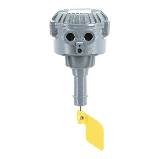
PFG57L
POWER
SUPPLY
Page 3 of 4