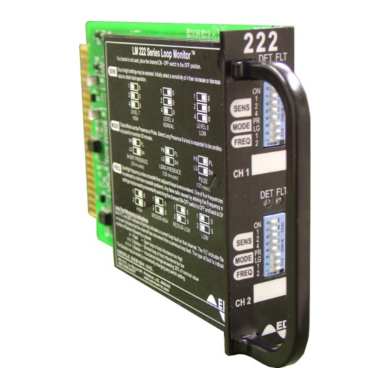
EDI 222 Series Panduan Pengoperasian - Halaman 6
Jelajahi secara online atau unduh pdf Panduan Pengoperasian untuk Sensor Keamanan EDI 222 Series. EDI 222 Series 17 halaman. Inductive loop detector sensor unit

shield may be connected to earth at the cabinet end but should then be insulated and isolated from
earth ground at the loop end.
Make sure that the loop wire is pushed fully to the bottom of the saw slot. Small pieces of foam rubber
or similar material may be used at various points around the circumference to prevent the loop wire
from rising up while the sealant is poured.
Many different typed of loop sealant are now available. Single part types are the easiest to apply
since no mixing is required, but they also tend to be more expensive in terms of linear feet of saw slot
filled. When applying the sealant, make sure that it is able to sink to the bottom of the slot and
completely encase the loop wire. The wire should not be able to move when the sealant has set.
Ensure that there is enough sealant to completely fill the slot; if possible the sealant should protrude
slightly above the surface of the pavement so that small rocks or other debris cannot collect in the
slot. The sealant manufacturer's instructions concerning setting time should be noted—especially
when determining the length of time to wait before allowing vehicles to cross the loop area.
1.6 THEORY OF OPERATION
1.6.1 SYSTEM DESCRIPTION
The Model 222 works on the principle of measuring the period of a pre-determined number of cycles
from an oscillator whose frequency is directly related to the inductance of the loop. The measurement
is done by counting the number of cycles of a stable crystal oscillator reference that occur during the
period to be measured. This scheme provides a high resolution measurement in a short period of
time. Consecutive measurements are compared with a reference that has been established to
determine whether or not the frequency of the loop oscillator has changed sufficiently to indicate the
presence of a vehicle. Each channel is sequentially scanned so that only one loop oscillator is
energized at any time.
The sensor circuitry can be broken down into four major blocks. The loop oscillators, digital
processing circuitry, switch controls and the outputs/indicators. Each oscillator input incorporates a
transformer to isolate the loop from the internal oscillator circuitry. Surge arrestors are provided to
protect the unit from transient electrical damage. The Loop oscillator frequency may be modified to
avoid crosstalk problems by switching capacitors into or out of the oscillator circuit. The output signals
from the oscillators are fed through squaring circuits before being supplied to the digital processing
circuit. Although the Model 222 has two loop oscillators, a single digital processing section is used to
measure the period of both oscillators in sequence.
The microcontroller determines the requisite number of loop oscillator cycles over which to perform
the measurement. It then provides this number to the digital processing section and a measurement
is initiated. When the sample period has ended, the sample value is collected and processed by the
microcontroller while another sample is initiated.
Eberle Design Inc.
Model 222
Operations Manual
Loop
Oscillator
Ch 1
Digital
Processing
Loop
Oscillator
Ch 2
Reference
Oscillator
Ch 1
Switches
Ch 2
Switches
Micro-
Controller
Ch 1
LEDs
Ch 2
LEDs
Page 4
