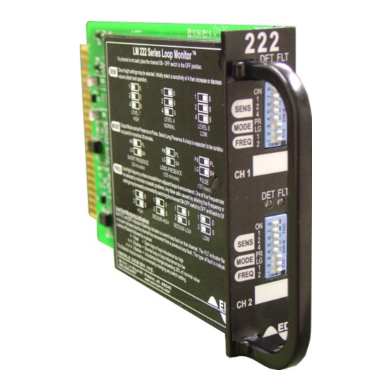
EDI 222 Series Panduan Pengoperasian - Halaman 9
Jelajahi secara online atau unduh pdf Panduan Pengoperasian untuk Sensor Keamanan EDI 222 Series. EDI 222 Series 17 halaman. Inductive loop detector sensor unit

1.7.2 TROUBLE SHOOTING SEQUENCE CHART.
Apply 24 VDC power to the unit (pin J1-B) referenced to Logic Ground (pin J1-A). Connect 100
microhenry inductors to the loop inputs pins J1-D (J1-J) and J1-E (J1-K) to simulate the connection of
loops. The following signal measurements are referenced to Logic Ground (pin J1-A):
a. Unregulated Power Supply.
Voltage at test point V_UNREG should be 24 1 Vdc.
Possible component faults are: diode CR11, resistor R13, capacitors C6-C7, or voltage
regulator VR1.
b. Regulated Power Supply.
Voltage at test point VDD should be 5 0.2 Vdc.
Possible component faults are: voltage regulator VR1.
c. Microcontroller Clock.
Waveform at pin 6 of U4 should be a square wave at 22.118 MHz.
Possible components at fault are: Crystal XTL1, U4.
d. Reset Input to Microcontroller.
Voltage at pin 35 of U3 should be less than 0.5 Vdc.
Possible components at fault are: U5-D, U4-C, microcontroller U3.
e. Loop Oscillator Output.
Connect one channel of a dual channel oscilloscope to test point ENABLE1 (ENABLE2).
Select trigger on the rising edge of this signal. Using the other channel of the oscilloscope,
monitor test point LP1 (LP2). The signal should be as follows:
Repeat the above for the second loop detector channel. If the above waveform is not found on
one or both channels of the detector, possible fault areas are Q8 (Q9), Q11 (Q13), Q7-A (Q7-
B), CR13 (CR14), or T1 (T2).
f. Outputs and Indicators.
Monitor the outputs so that when the channel is in the detect state, the outputs can be seen to
be conducting. Enter a detect condition by bringing an aluminum or similar non-ferromagnetic
object close to each simulated loop. The DET indicator should illuminate and the opto-isolated
output U1 (U2) should be conducting.
Possible components at fault are: opto-isolator U1 (U2), CR2 (CR7), or LED DS1 (DS2).
Eberle Design Inc.
Model 222
Operations Manual
Page 7
