Altronic CDM-2100 Panduan Pengoperasian - Halaman 4
Jelajahi secara online atau unduh pdf Panduan Pengoperasian untuk Alat Ukur Altronic CDM-2100. Altronic CDM-2100 20 halaman. Differential pressure monitor

5.0 WIRING
(SEE WIRING DIAGRAM, FIG. 2)
5.1
Wire Cable Assembly 693158-XX, where XX may be -60, -120, -360 (which
represents the cable length in inches) cabling, into the panel. This assembly
contains the wiring for the connection to the differential pressure transmitter.
Feed the cable through the bottom of the panel and connect each wire to its
appropriate position on the terminal strips. Separate power wiring must be routed
to the panel, and must follow guidelines published by the NEC and local authority.
6.0 KEYPAD DESCRIPTION
6.1
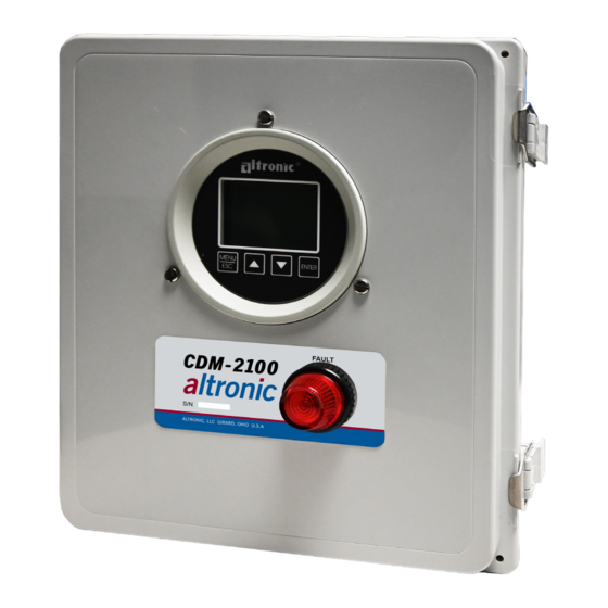
The CDM-2100 gauge features a four-key front keypad which is used to view or
change the setpoint values, configure and calibrate the gauge. The front panel
keys are MENU/ESC, ENTER, and , (up and down arrow keys).
6.2 MENU/ESC
The MENU/ESC key is used to enter the main menu and to return to the home
screen at any time. If the MENU/ESC key is used to return to the home screen
prior to pressing the ENTER key, changes are not stored in the memory and do
not take effect.
6.3 ENTER
The ENTER key is used throughout the menu to proceed through the
configuration and to accept the data to be saved. Throughout configuration
when a change has been made and is to be saved to memory, press ENTER and
the display will read SAVED, and the new data or configuration will be stored in
the nonvolatile memory.
6.4 AND
The up and down arrow keys are used to scroll through the selections in the
menu and to increase or decrease values during configuration and calibrations.
Values can be changed incrementally using individual key presses or more
rapidly by holding the key down.
7.0 UNDERSTANDING THE HOME SCREEN
7.1
The CDM-2100 is considered in the HOME SCREEN when measuring and
displaying monitored data. The gauge displays up to a 5-digit numeric value
in 0.5" numbers, units of measure, the monitored point label, and a graph if
enabled. If a setpoint is configured and its value is exceeded, the output switch
turns on and the display will indicate SW1 LO, SW1 HI, SW2 LO or SW2 HI (low,
or high setpoint and switch 1 or 2 has tripped).
When the displayed reading exceeds the upper limit of the gauge (110% of
range), the display will read INPUT SIGNAL IS HI OUT OF RANGE, and if
configured, its high output switch will activate. If the displayed reading exceeds
the lower limit of the gauge, the display will read INPUT SIGNAL IS LO OUT OF
RANGE, and if configured, its low output switch will activate.
DIF F E R E N TIA L
1 2 .0 m A
CDM-2100 OM 3-21
All rights reserved © ALTRONIC, LLC 2021
0
in H 2 0
4
NOTE: All furnished drawings and
instructions assume (–) ground DC
system. In the case of a floating
ground, or (+) ground DC system,
please contact Altronic Factory for
support.
