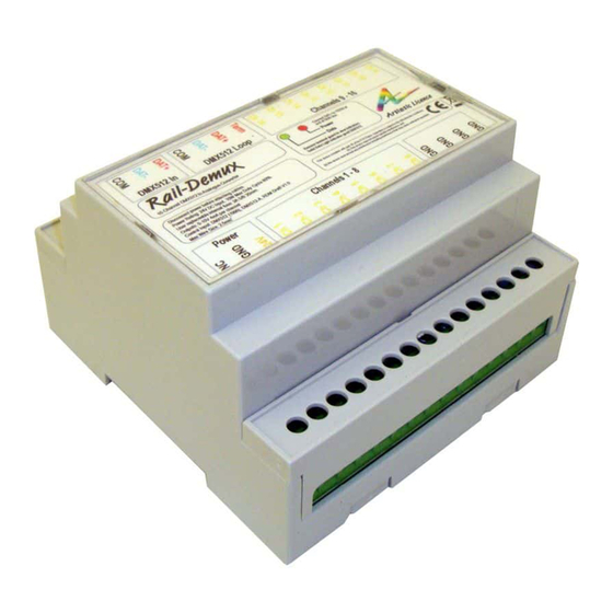
Artistic Licence Rail-Demux Panduan Pengguna - Halaman 5
Jelajahi secara online atau unduh pdf Panduan Pengguna untuk Konverter Media Artistic Licence Rail-Demux. Artistic Licence Rail-Demux 9 halaman.

Summary of Key Features
16 Analogue outputs ANSI E1.3 - 2001
y
(R2016)
0 - 10 VDC output
y
DMX512 Interface
y
RDM V1.0 (E1.20 - 2010)
y
DIN rail mount
y
Surface mount
y
Operation
To adjust or calibrate the output of the Rail-
Demux, use the following procedure:
Disconnect the power supply.
1.
Gently remove the lid of the DIN rail unit.
2.
Locate the calibration resistor (RV1).
3.
This will allow you to decrease or
increase the output voltage range.
Replace lid and reconnect to the power
4.
supply.
Ensure that you are grounded before touching
any internal components. You can achieve
this by either wearing an anti-static wristband
or by touching an earthed metal surface at
regular intervals.
Power
Rail-Demux is be powered from an external
DC power supply (24 VDC). It is recommended
that a ferrite core be fitted onto the DC power
lines as close as possible to the Rail-Demux.
This protects the unit from any electrical spikes
that appear on the DC line.
Rail-Demux User Guide
LED Indication
Rail-Demux has green and red LED indicators
under the terminal guard. The display is as
follows:
Data (left):
OFF = No data received
Solid green = Data received
Flashing green = Test mode (see 'Configuration'
section)
Power (right):
Solid red = Power
Flashing red = Identify
Connections
Please refer to the connections diagram.
DMX512 Input & Loop-Through
The DMX512 input is via a 3-pin screw
terminal.
A 4-pin screw terminal passive loop-through
connection allows onward connection to other
DMX512 devices. This enables two or more
Rail-Demux units to be connected in parallel
to increase the number of outputs.
If this feature is not required then the signal
must be terminated. The product contains an
internal termination resistor. This is enabled by
fitting a wire link between the screw terminals
that will terminate the DMX line (Term and
DAT+).
Analogue Outputs
Two 8-pin screw terminals are used for the 16
analogue outputs. The standard that defines
the output is ANSI E1.3 - 2001 (R2016).
Output Ground
One 4-pin screw terminal is used for the ground
connection. Multiple control ground wires can
be connected to each of the terminals.
Page 5
