DLI DLM-4 ZONE Manual - Halaman 3
Jelajahi secara online atau unduh pdf Manual untuk Pengontrol DLI DLM-4 ZONE. DLI DLM-4 ZONE 19 halaman.
2. Facts
Here are some important things to consider when using the DLM-4
Zone Controller.
•
A maximum of 255 ballasts and 1 temperature sensor can be
connected to each zone on the DLM-4 ZONE.
•
A maximum distance of 1000ft / 300 meters between the DLM-4
ZONE and the ballasts to be controlled.
•
Each zone MUST have a single wattage / type of fixture connected
to it. You cannot mix fixtures with different wattages on the same
zone interconnect wiring.
•
A single low-volt cable is used to interconnect the DLM-4 ZONE
to the fixtures within each zone. Various length pre-crimped RJ12
cables and additional interconnect splitters can be purchased
separately.
•
Ballast control is connected using RJ12 cables which are used to
daisy-chain the fixtures together. Each of the ballasts comes with
an RJ12 "T" splitter.
•
Each individual zone can have its own temperature sensor for more
accurate control.
•
It is also possible to "assign" a specific temperature sensor to link
with more than one lighting zone.
•
Each temperature sensor can be connected anywhere within the
growing area. Temperature sensors are connected using the same
RJ12 cables and "T" splitters.
•
Follow all local and national electrical codes for installation
requirements.
04
DLM-4 ZONE
Controller
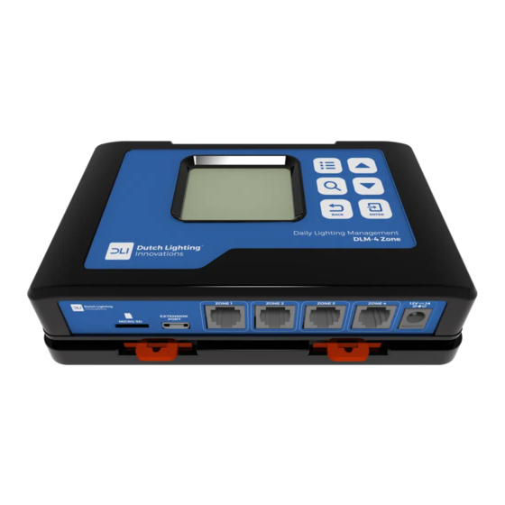
3. Components
3
1
Controller
2
Back Plate
3
Screws and anchors for back plate and temperature sensor
4
16 ft RJ12 cable
5
4 ft RJ12 cable
6
Temperature sensor
7
T splitter
8
12 VDC Power supply
1
6
4
5
DLM-4 ZONE
Controller
2
7
8
05