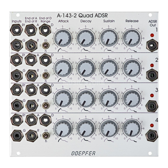
DOEPFER A-143-2 Manual - Halaman 5
Jelajahi secara online atau unduh pdf Manual untuk Peralatan Perekaman DOEPFER A-143-2. DOEPFER A-143-2 6 halaman. System a-100, quad adsr

DOEPFER
DOEPFER
DOEPFER
DOEPFER
3. Controls, Inputs and Outputs
!
G :
gate input
$
Rt :
retrigger input
Socket ! is the ADSR's gate input, socket
input. The detailed function of these inputs is described on
page 2.
The gate inputs of the units 2...4 are normalled to the gate
input of unit 1. If one common gate signal has to be used for
all four units this signal has to be patched into the gate input
of unit 1. As soon as a plug is inserted into the gate input 2,
3 or 4 the default connection is interrupted for the unit in
question.
The retrigger inputs are not normalled.
1
Range :
range switch low – high – medium
2
Attack :
attack control
3
Decay :
decay control
4
Sustain :
sustain control
5
Release :
release control
These controls define the ADSR shape. The rotary controls
2
3
4
5
,
,
and
are used to adjust the attack time, the
decay time, the sustain level and the release time. The
1
range switch
is used to select one of three time ranges
for the time controls attack, decay and release. The
meaning of attack, decay, sustain and release is described
in detail on page 2.
System A-100
&
6
Socket
envelope voltage ranges from 0 to about +8V. The envelope
$
the retrigger
signal is displayed with the LED
"
§
%
These are three digital outputs that indicate the end of the
attack, decay or release phase. As soon as the criterion in
question is valid, the corresponding digital output turns
"high". The three digital outputs are described in detail on
page 2. The output levels are about +10V.
These outputs can be used to trigger other A-100 modules
(or another unit of the A-143-2) synchronized to the ADSR
envelope generated by the A-143-2.
Quad ADSR A-143-2
ADSR Out:
envelope output
:
envelope display (LED)
&
is the output of the envelope generator. The
End of A :
end of attack output
End of D :
end of decay output
End of R :
end of release output
6
.
5
