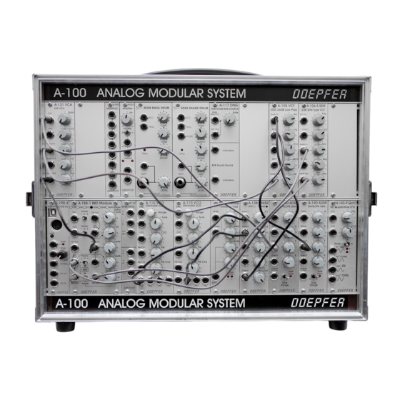
DOEPFER A-105 Manual - Halaman 5
Jelajahi secara online atau unduh pdf Manual untuk Pengontrol DOEPFER A-105. DOEPFER A-105 8 halaman.

doepfer
$ QCV
This socket is the voltage control input for the filter's
resonance.
If you patch a modulation source (eg LFO, ADSR) to
this input, the resonance of the filter will be modulated
by it: increases in voltage will increase the amplitude
of the frequencies around the filter cut-off point.
% Audio Out
Filter output % sends out the filtered audio signal.
System A - 100
5. User examples
The filter's cut-off frequency can be modulated in
various ways:
• VCF - LFO
Modulation of the cut-off frequency produces cycli-
cal changes of the sound spectrum. At low fre-
quencies (c. 1 - 5 Hz), you get a "Wah-Wah"
effect. Modulation in the audio range produces
interesting sounds; the same principles apply here
as with frequency modulation of the A-110 VCO
(see chapter 6).
• VCF - ADSR
Modulation by an envelope results in gradual
change of the sound spectrum. Typical uses
would be the synthesis of electric bass or drum
sounds, and filter sweeps, which slowly sweep
through the audio spectrum, emphasising different
harmonics.
• VCF - Keyboard CV
This modulation produces pitch-related filter ope-
ning: the higher the pitch, the more the filter opens,
and the brighter the sound becomes.
24 dB Bandpass
By combining the A-123 high pass filter with the A-122
low pass filter, it's possible to create 24 dB band
pass or 24 dB notch filters (as opposed to the
A-105 / A-122
•
24 dB Notch
5
