AERMEC CR Series Petunjuk Penggunaan Manual - Halaman 12
Jelajahi secara online atau unduh pdf Petunjuk Penggunaan Manual untuk Pompa Panas AERMEC CR Series. AERMEC CR Series 16 halaman. Chillers and heat pumps

MODIFICA DEI VALORI DI TARATURA
1 Visualizzare il parametro da modificare come indicato nel
paragrafo "Visualizzazione dei parametri di funzionamen-
to".
2 Premere il tasto
. Se la spia gialla SET inizia a lampeg-
giare significa che il parametro in questione può essere
modificato; in questo caso passare al punto 4.
Se, invece, compare la scritta
introdurre il codice d'accesso per modificare il parametro;
in questo caso passare al punto 3.
3 Introdurre il proprio codice d'accesso, visualizzato sul
display a 3 cifre tramite i tasti
. Se il codice è corretto
allora la spia gialla SET inizia a lampeggiare ed è possibile
modificare il parametro. Se, invece, il codice non è corret-
to, occorre ripartire dal punto 2.
4 Modificare tramite i tasti
selezionato. Per confermare la modifica premere il tasto
, altrimenti per annullare la modifica premere il tasto
SEL. Se la modifica viene confermata allora sul display
appare per pochi istanti la scritta
un'operazione di scrittura sulla memoria permanente della
Scheda Controllo.
VISUALIZZAZIONE DELLA TERMOSTATAZIONE
A seconda del funzionamento della macchina la spia verde
assume i seguenti significati:
spenta: il termostato non da consenso alla partenza e il
compressore è fermo.
accesa: il termostato da consenso al funzionamento e il
compressore è in funzione.
il termostato da consenso alla partenza ma il
lampeggiante:
compressore è in attesa. Questo può succe-
dere in quanto il numero massimo di accen-
sioni in un'ora è 6. Per ottimizzarne, quindi,
il funzionamento, viene controllato che tra
un sua accensione e la successiva siano tra-
scorsi almeno 9 minuti.
A questi 9 minuti bisogna aggiungere il
tempo Attesa OFF-ON compressore che per
le unità NRW è fisso ad 1 minuto, per le
unità AN e CR, invece, è impostabile da un
minimo di 1 minuto ad un massimo di 10
minuti.
VISUALIZZAZIONE DELLO SBRINAMENTO (CR H)
Il microprocessore controlla la temperatura della sonda nella
batteria e il tempo trascorso dall'ultimo sbrinamento, con
queste informazioni il microprocessore, autonomamente,
imposta il nuovo set di sbrinamento ottimizzando così il fun-
zionamento della macchina.
A seconda del funzionamento dell'unità la spia gialla
assume i seguenti significati:
spenta: funzionamento normale dell'unità.
accesa: sbrinamento in corso.
c'è il consenso per l'inizio dello sbrinamen-
lampeggiante:
to, ma non è ancora trascorso il tempo mini-
mo necessario tra uno sbrinamento e l'altro.
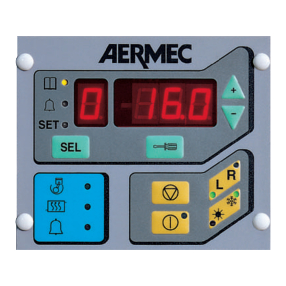
PANNELLO COMANDI REMOTO – PR –
Di seguito sono descritte le funzionalità del Pannello Remoto
(accessorio PR per NRW, di serie per CR) di fig. 1:
1) Interruttore acceso / spento (stand-by);
2) Commutatore funzionamento invernale / estivo;
3) Segnalazione intervento allarmi.
Per effettuare un Reset dal Pannello Remoto, premere in
sequenza veloce il pulsante di spegnimento accensione.
12
, significa che bisogna
-
, e premere il tasto
+
il valore del parametro
-
+
, che rappresenta
MODIFYING CALIBRATION VALUES
1 Display the parameter for modification; see paragraph
"Display of operating parameters".
2 Press the
key. If the yellow SET lamp starts flashing, the
parameter can be modified. Move on to point 4.
If the
message appears, the password must be ente-
red to modify the parameter. Go to point 3.
-
3 Use the
keys to enter the password, shown on the
+
display in 3 digits, then press the
is correct, the yellow SET lamp will start flashing and the
parameter can be modified. If the password entered is
incorrect, return to point 2.
-
4 Use the
keys to modify the selected parameter. To
+
confirm the modification, press
tion by pressing the SEL key. When the modification is con-
firmed, the display will momentarily show the
ge, which represents a writing operation in the permanent
memory of the Control card.
THERMOSTAT DISPLAY
On the basis of the current machine operation, the green
lamp
has the following meanings:
off: the thermostat does not give permissive for start-up, com-
pressor is off.
on: the thermostat gives permissive for start-up, compressor is
on.
flashing: the thermostat gives permissive for start-up, but
compressor is in stand-by status. This condition is
possible because the maximum number of start-up
operations in an hour is six. To optimise operation,
make sure that there is an interval of at least 9 minu-
tes between start-ups.
To the 9 minutes add the compressor OFF-ON
stand-by time: 1 minute in the case of NRW units, 1
- 10 minutes in the case of AN and CR units.
DEFROSTING DISPLAY (CR H)
The microprocessor controls the coil probe temperature and
the time elapsed since the last defrost. On the basis of this
information, the microprocessor automatically selects a new
defrost setting, thereby optimising unit operation efficiency.
Depending on unit operation mode, the yellow lamp
indicates:
off: routine unit operation.
on: defrosting in progress.
flashing: permissive for defrosting, though minimum time
necessary between defrosting operations has not
elapsed.
REMOTE CONTROL PANEL – PR –
The following is a description of remote control functions (see
fig. 1). The panel is an accessory PR for NRW units, standard
equipment on CR models:
1) ON/OFF (stand-by) switch;
2) Winter / summer changeover switch
3) Summation alarm signal.
To reset from the Remote Control Panel, jog the ON/OFF swit-
ch rapidly.
key. If the password
, or erase the modifica-
messa-
