Clopay EZ-SET Petunjuk Perakitan/Pemasangan - Halaman 7
Jelajahi secara online atau unduh pdf Petunjuk Perakitan/Pemasangan untuk Pembuka Pintu Garasi Clopay EZ-SET. Clopay EZ-SET 12 halaman. Torsion spring system
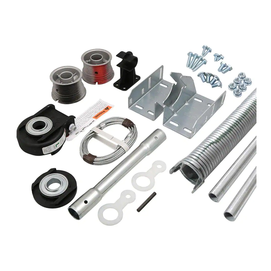
Step 4
carefully lift up the torsion tube and components
and place the ends of the tube in the cradle of
each bracket. pull the tube away from the bracket
to slide the drum in between the bracket legs, and
engage the winding unit rails in the bracket slot.
(FIg. 10, VIEW A) Push the winding unit rails into
the bracket until the unit bottoms out.
If you have a door with two springs, go to the right
side and repeat the procedure for installing the
winding unit in the bracket.
If you have a door with only one spring, go to the
right side and install the end bearing support. The
end bearing support is installed in the same man-
ner as the winding unit. pull the tube back just far
enough to place the drum between the legs of the
bracket. Do not pull the tube further than needed
to move the end bearing support and drum into
place, as damage may occur to a unit that is en-
gaged on the other side. Line up the
end bearing support rails (making sure that the
orientation feature is facing away from the brack-
et) and push it into the bracket until it
bottoms out. (FIg. 10, VIEW B)
center the tube as equally as possible between
the brackets, so that an equal amount of the tube
is extending from each side.
Step 5 (doors over 10' wide only)
NOTE: Before installing
important to drill
/
" pilot holes where the lag
1
8
screws are to be attached.
Snap the center support onto the center of the
torsion tube (or coupler if present). Fasten the
support with two
/
" x 1" lag screws to the header
1
4
above the center of the door. The lag screws
should be located at opposite corners of the
center support as shown in Figure 11. Position
and shim the mounting location as required to
make the tube straight. check the distance from
the top of the door and the wall or header to the
tube along the length of the door to make sure the
tube is straight and level.
/
" lag screws, it is
1
4
Winding Unit
Bracket
VIEW A
lEfT SIdE ShOWN
End Bearing
Support
Bearing
Rails
VIEW B
SINGlE SPRING – RIGhT SIdE ShOWN
fig. 10
NOTE: The drums and torsion tube are removed
from figure 10, View A and figure 10, View B
for clarity.
header or Wood
Anchor pad
Torsion
Tube
fig. 11
Bearing
Rails
Orientation features
Bracket
Torsion
Tube
lag
Screws
Coupler
Center Support
(Required on doors
over 10' wide only)
7