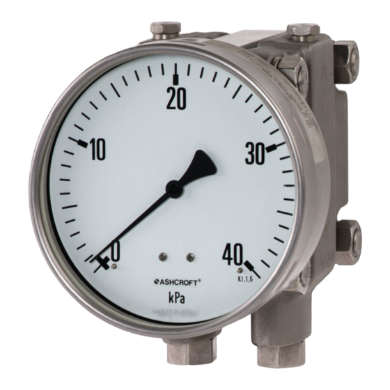
Ashcroft 5503 Series Panduan Petunjuk Pemasangan dan Pemeliharaan - Halaman 3
Jelajahi secara online atau unduh pdf Panduan Petunjuk Pemasangan dan Pemeliharaan untuk Alat Ukur Ashcroft 5503 Series. Ashcroft 5503 Series 7 halaman. Differential pressure gauges

Installation and Maintenance Instructions for
5503 Differential Pressure Gauges
5 CONSTRUCTION & FUNCTION
5.1 Overview
1. Connecting rod
2. O-Ring, differential
overpressure protection
3. Sensing diaphragm
4. Movement
5. Lever
6. Link
7. Pressure transfer liquid.
5.2 Description of function
The pressures to be compared act on flexible stainless steel
diaphragms on either side of the sensing capsule. The
diaphragms are mechanically linked by a rigid connecting rod.
To compensate high static pressures, the cavity between the
two diaphragms is filled with hydraulic fluid. When pressures
are equal on both diaphragms, they are at zero position. When
there is a difference in pressures acting on the two diaphragms,
they are deflected away from the high pressure side, towards
the lower pressure side, causing a displacement of the con-
necting rod.
A precision mechanism translates the linear displacement of the
diaphragm connecting rod to angular movement of the gauge's
dial pointer. The pointer's displacement range of 270° corre-
sponds to the full scale differential pressure. The connecting
rod has intermediate flanges on either side, which protects the
diaphragms against excess differential pressure.
When differential pressure exceeds the specified limit, the flange
towards the lower pressure side is pressed against the sealing
O-ring on the inside of the sensing capsule. This action isolates
the fluid adjacent to the diaphragm exposed to lower pressure,
from the fluid at higher pressure on the other side. This limits the
pressure differential across the lower pressure diaphragm, and
equalizes the pressure across the higher pressure diaphragm.
Thus both diaphragms are protected against excess deflection
and risks of rupturing. The model F5503-XSP is designed for
higher static pressure than the F5503 with stronger pressure
chambers and mounting parts.
5.1 Description of components
5.1.1 Dial scale and pointer
The differential pressure gauge is equipped with a dial face and
pointer pursuant to DIN 16003, nominal size 100 mm or 160 mm.
5.1.2 Instrument connection
The instrument connection is located on the underside of the
differential pressure gauge and can be a threaded or flanged
similar to DIN EN 61518.
© Ashcroft Inc. 2019, 250 East Main Street, Stratford, CT 06614-5145, USA, Tel: 203-378-8281, Fax: 203-385-0357, www.ashcroft.com
All sales subject to standard terms and conditions of sale. 5503_gauge_i&m_RevA_07-18-19
5.1.3 Vent and flushing connection
The vent and flushing connection of each pressure chamber is
located on its top side. It is closed by a screwed in G
5.2 Accessories
The use of a 3 or 5 valve manifold is highly reccomended.
Please contact Ashcroft or your Ashcroft representative
regarding available special tools and accessories.
6 TRANSPORT
6.1 Safety
The differential pressure gauge should be protected against
the effects of knocks and impacts. The device should only be
transported in the packaging provided, to protect against glass
breakage. The device should only be transported in a clean
condition (free of residues of measuring media)
6.2 Transport inspection
The delivery must be checked for completeness and damage
during transport. In the event of damage during transport, the
two
delivery must not be accepted, or only accepted subject to
reservation of the scope of the damage being recorded and, if
necessary, a complaint initiated
6.3 Storage
The differential pressure gauge must be stored in dry, clean
conditions, within a temperature range of -40 to 160°F (-40
to +70 °C), protected against direct exposure to sunlight and
protected against impact damage
7 ASSEMBLY/INSTALLATION
7.1 Safety
To ensure safe working during installation and servicing,
suitable shut-off valves must be installed (see 5.2 Accessories),
enabling the device:
• To be depressurized or taken out of operation;
• To be disconnected from the main pressure source for repair
or checks within the relevant plant;
• Or to enable function tests of the device to be performed "on
site".
During the mounting/installation of the gauge, the equipment
must be protected against the main pressure source and elec-
trical connections isolated from being switched back on.
7.2 Preparations (requirements for the installation location)
• A check on suitability of the device for the medium to be
measured, the scope of the measurement range and static
pressure and of the protection against special conditions such
as vibration, pulsation and pressure spikes.
• A bracket must be installed to support the pressure gauge if
the process pipe is not able to provide adequate support.
• The installation location should be chosen such that the
work-spaces for operating personnel are not located to the
rear of the pressure gauge.
⁄
plug
1
8
.
3
