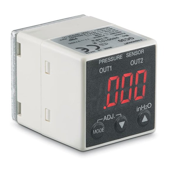
Ashcroft GC30 Panduan Petunjuk Pemasangan dan Pemeliharaan - Halaman 13
Jelajahi secara online atau unduh pdf Panduan Petunjuk Pemasangan dan Pemeliharaan untuk Aksesori Ashcroft GC30. Ashcroft GC30 20 halaman. Ultra-compact digital
differential pressure transducer
Juga untuk Ashcroft GC30: Panduan Memulai Cepat (7 halaman)

9C. SeleCTING STANDArD Or CUSTOM SCAlING MODe
et
When the
displays as an arbitrary scaling display. This is a function to scale the MIN/MAX display value
and has NO effect on applied pressure and analog output.
9D. CUSTOM SCAlING MODe
Use the MODE key to set "Decimal point position", "Minimum pressure range display value"
and Maximum pressure range display value" of "Display scaling".
Example: With a pressure range of 0 to 25inWC (0 to 100% FS), main unit display of 00.0 to
25.0 (factory set) is changed to a display of 0.000 to 1.000.
d-p Dec. point position (from least significant digit):
d-l Min. pressure range value:
d-k Max. pressure range value:
9e. fIlTer SeCTION
The GC30 is equipped with 5 internal time constant filters. Use this function when pressure
fluctuations can result in erratic, difficult to read displays. The time constant for the selected fil
ters reflects on the switch outputs as well as the analog output.
Select "Filter Selection" with the MODE key. The message f;l is displayed for 1 sec. and
then the current setting mode's decimal point position is displayed. Change the decimal point
position value with the
Entering the setting value in function setting mode resets all of the setting
f-0
No filter
f-1
Time constant 25ms
f-2
Time constant 250ms
f-3
Time constant 2.5 sec
f-4
Time constant 5 sec
f-5
Time constant 10 sec
9f. ANAlOG OUTPUT SCAlING
This mode is for setting the pressure for the analog output zero point and span point. Display
by analog selection is scaled as 0 to 100% (Zero point: 1Vdc, Span: 5Vdc). Select "Analog
Scaling" with the MODE key.
The message
point (1Vdc) is displayed as a percentage. Change the numeric value with the
The message
be set in the same way using the
example: With Analog output of 1 to 5Vdc at pressure range of 0 to 10.0in WC (0 to 100%
FS), output is changed to 1 to 5Vdc at 0 to 9.0inWC.
Set the analog output zero point: 0.0% FS 0.0% FS (1Vdc output with pressure range 0% FS).
Set the analog output span point: 100.0% FS 90% FS (5Vdc output with pressure range 90% FS).
10. SwITCh SeTTINGS MODe
Setup Steps
In Measurement Mode press the key (release within 3 sec.) to change to Switch Setting
Mode.
Switch Setting Mode
There are two switches, OUT1 and OUT2. Both "Hysteresis (upper/lower limit)" and "Window
Comparator" operations can be selected in the function setting mode (switch operation selec-
tion). Those two operations can be selected at once, and can be set. Both OUT1 and OUT2
can be set independently to a max on/off delay of 2 seconds. In the following explanation -
If the switch's output conditions are met their output state will become On, and "Switch LED
(OUT1, OUT2)" will light up.
is selected in "Display Selection", the display value of Pressure for applied
keys.
a-l is displayed for 1 sec. and the current pressure's analog output zero
a-k is displayed for 1 sec. and the analog output span point's pressure can
keys.
13
0.1 Ÿ
.003
0.0 Ÿ
.000
25.0 Ÿ 1.000
keys.
