CYP CH-1109TXC Panduan Pengoperasian - Halaman 8
Jelajahi secara online atau unduh pdf Panduan Pengoperasian untuk Pemanjang CYP CH-1109TXC. CYP CH-1109TXC 13 halaman. Hdmi to cat5e/6 with lan/poe/ir extender
Juga untuk CYP CH-1109TXC: Panduan Pengoperasian (18 halaman)

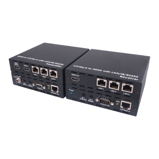
6.2 Receiver Front and Rear Panels
Front
Power
IR 1
IR 2
Extender Blaster
1
2
3
Power LED: The red LED will illuminate when the 24 V DC Adaptor is
1
connected to the AC outlet.
IR 1 Extender: Connect with the IR receiver cables (included in the
2
package) for IR signal reception. The related IR transmitter port is
IR1 Blaster.
IR 2 Blaster: Connect t with he IR blaster cables (included in the
3
package) for IR signal transmission. The related IR receiver port is
IR2 Extender.
4
RS-232 Out: Connect to a RS-232 enabled device (with a D-Sub
9-pin female cable) for the transmission of RS-232 commands.
Link LED: This yellow LED will illuminate when the both CAT5e/6
5
input and output signal is connected.
CAT5e/6 In: Connect the transmitter and receiver via a single
6
CAT5e/6 type cable for all data transmission.
HDMI Out: Connect to a HDMI equipped TV or monitor to display
7
the HDMI input source signal.
8
LAN 1/2/3: The LAN connections can be used to connect and
share up to 6 ethernet connections (3 at the reciver end, 3 at the
transmitter end), including computers, routers and media servers.
Link
RS232 Out
CAT5e/6 In
4
5
6
Rear
HDMI Out
LAN 1
7
LAN 2
LAN 3
8
4
