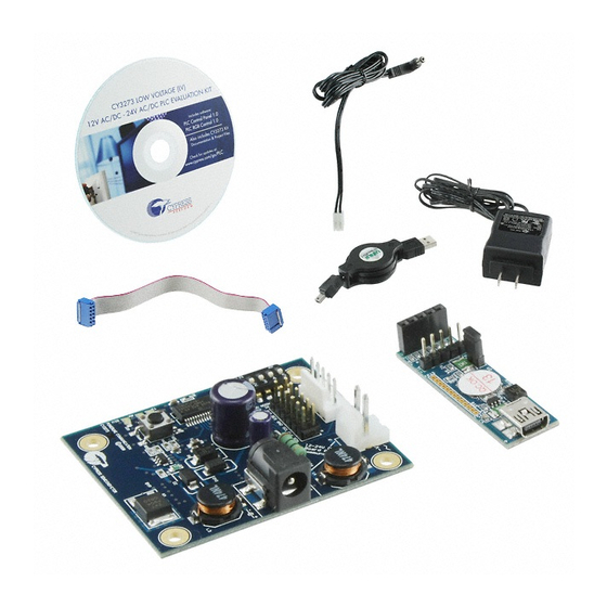
Cypress CY3273 Panduan Memulai Cepat - Halaman 2
Jelajahi secara online atau unduh pdf Panduan Memulai Cepat untuk Motherboard Cypress CY3273. Cypress CY3273 2 halaman.

CY3273 QUICK START GUIDE
1
Connect the power adapter from the
mains to header J4 on the first CY3273
board (node 1). The blue LED turns on.
3
Attach one end of the USB-I
J8 on node 1. With the mini USB cable, connect
the Bridge to the PC. The green LED must turn on.
Note: Connect only one USB-I2C Bridge for
each PC. For more details, refer to Section 1.3 in
the PLC Control Panel User's Guide.
For the latest information about this kit visit
www.cypress.com/go/plc
© 2009-2011 Cypress Semiconductor Corporation. All rights reserved. All trademarks or registered trademarks referenced herein are the
properties of their respective owners.
2
C Bridge to header
2
Attach one end of the custom daisy chain cable
to header J1 on node 1 (connector hook facing
in). Connect the other end to header J4 on the
second CY3273 board (node 2). The blue LED
turns on.
4
1. Install and run the PLC Control Panel GUI
from the CY3273 kit CD. Download the
latest revision from the software and drivers
link at www.cypress.com/go/plc.
2. Follow the instructions in Section 1.3 of the
PLC Control Panel User's Guide to
communicate between nodes 1 and 2. To
open the user's guide from the GUI, click
Help > Users Guide from the menu bar.
DOC#: 001-54835 REV *D
