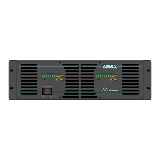
Ashly MFA-6000 Panduan Pengoperasian - Halaman 8
Jelajahi secara online atau unduh pdf Panduan Pengoperasian untuk Penguat Ashly MFA-6000. Ashly MFA-6000 20 halaman. Ashly audio corporation operating manual power amplifier mfa-8000, mfa-6000

Operating Manual - MFA-8000 and MFA-6000 Power Amplifier
Figure 7: Input Section
7.
REAR PANEL FEATURES
7.1
Inputs
The standard input panel of the MFA series amps
is equipped with balanced 1/4" tip-ring-sleeve (TRS)
phone jacks, balanced XLR jacks, and balanced screw-
terminal inputs. The three types of connectors are inter-
nally wired in parallel and may be used with balanced or
unbalanced connections. The inputs are configured for
pin 2 hot, meaning that a positive voltage applied to pin 2
will result in a positive output voltage across the speaker
terminals. Pin 2 of the XLR jack is equivalent to the tip
of the 1/4" TRS jack. An optional input transformer is
available on all MFA amplifiers.
Balanced Inputs
It is recommended that balanced input connec-
tions be used whenever possible to reduce ground-loop
and environment-induced hum and noise. The (+) signal
is on pin 2 of the XLR, and the tip of the phone jack. The
(-) signal is on pin 3 of the XLR, and the ring of the phone
jack.
Unbalanced Inputs
If an unbalanced input connection is used, then
the (-) connection (XLR pin 3) should be connected to
input ground ( XLR pin 1). If the 1/4" input jack is used
unbalanced, the use of a mono (tip-sleeve) plug will au-
tomatically tie the (-) connection to input ground. Never
float pin 2 or pin 3 when using an unbalanced signal.
8
Normal
Bridging
0
-2
-
Parallel Mono Mode ties Ch.1 and Ch.2
-6
inputs together, using seperate level controls
for each channel.
-20
Bridge Mode uses Ch.1 input and Ch.1
-10
level control, overriding stereo/mono switch.
Channel Two
Take output from two red binding posts.
(-)
(+)
Channel Two Input
Stereo
Parallel Mono
Input
Ground
(-)
(+)
Chassis
Channel One Input
Ground
(Bridged Input)
Figure 7.1: Balanced Input Connections
Figure 7.1a: Unbalanced Input Connections
0
-2
-
-6
-20
-10
Channel One
