Cypress CH-2507TX Panduan Pengoperasian - Halaman 9
Jelajahi secara online atau unduh pdf Panduan Pengoperasian untuk Beralih Cypress CH-2507TX. Cypress CH-2507TX 16 halaman. Hdmi to cat5e/6/7 transmitter and receiver with lan/ir/rs-232/poe

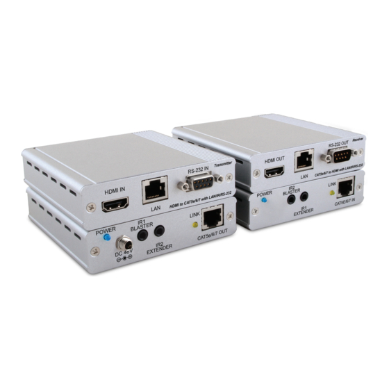
6.2 Receiver Front and Rear Panels
Front
HDMI Out
1
2
HDMI OUT: Connect to a HDMI equipped TV/monitor for display of
1
the HDMI input source signal.
LAN: Connect to a LAN equipped device (such as a smart TV or
2
games console) to share the network access (including internet
access if available).
Warning: DO NOT connect the LAN connection to the CAT5e/6/7
output, doing so may trigger a power shut down and may damage
the device.
RS-232 OUT: Connect to the device that is to be controlled (via
3
D-Sub 9-pin female cable) by RS-232 commands.
POWER LED: This blue LED will illuminate when the device is
4
connected to a power supply.
IR2 BLASTER: Connect an IR Blaster cable for IR signal transmission.
5
IR signals received by an IR extender connected to the transmitter
unit will be transmitted by this blaster. Place the IR Blaster in direct
line-of-sight of the equipment to be controlled.
IR1 EXTENDER: Connect an IR Extender cable for IR signal reception.
6
Signals received will be transmitted from any IR blaster connected
to the tranmitter unit. Ensure that the remote being used is within
the direct line-of-sight of the IR Extender.
LINK LED: The yellow LED will illuminate when both the source
7
connected to the transmitter and the display connected to the
receiver are connected. The LED will blink regularly to indicate
that no signal is being received from the display and irregularly to
indicate that an error has occurred.
CAT5e/6/7 IN: Connect to the transmitter unit with a single
8
CAT5e/6/7 cable for transmission of all data signals.
Receiver
RS-232 Out
CAT5e/6/7 to HDMI with LAN/IR/RS232
3
Rear
IR2 Blaster
Power
IR1 Extender
5
4
6
7
8
4
