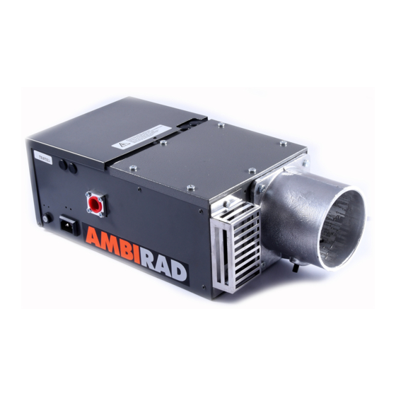
Ambirad AR22/27' SL Manuale di installazione e manutenzione - Pagina 15
Sfoglia online o scarica il pdf Manuale di installazione e manutenzione per Riscaldatore a gas Ambirad AR22/27' SL. Ambirad AR22/27' SL 20. Gas fired radiant tube heaters

- 1. Table of Contents
- 2. AR and ARE Series Gas Fired
- 3. Gas Connection
- 4. Standards
- 5. Assembly Instructions
- 6. Fitting Reflectors and End Caps
- 7. Burner/Fan/Damper Assembly
- 8. AR and ARE Series Double Linear
- 9. HB and DL Damper Settings
- 9. Installation – Suggested Methods
- 9. Of Heater Suspension
- 10. Flue Connection
- 11. Commissioning for Individually
- 12. Routine Service
- 13. Trouble Shooting Checklist
- 14. User Instructions for Ambi-Rad
13 Flue connection
The Ambi-Rad heater may be installed with
or without a flue to atmosphere providing
the air supply and building ventilation
requirements as stated in BS 6896:1991
complied with and providing due
consideration is given to the possibilities of
condensation forming on cold surfaces when
used as an unflued heater.
Unflued installation
Permanent ventilation required is as follows:
Natural ventilation
(to be fitted at high and low level with
minimum distance between of 3m).
Low level, when air change rate is less than
33m
3
/h/kW of total rated input, either:
1.4cm
2
for each 1m
3
/h/kW below 33m
or 46cm
2
/kW of total rated input.
High level, above areas where personnel are
working is as above.
Mechanical ventilation
Minimum proven air flow is 33m
total rated heated input.
If the heater is installed without a flue,
ensure that combustion gases do not
impinge on combustible materials. The
maximum permitted temperature for such
materials is 50 º C, EN416.
Flued installation
The Ambi-Rad heater may be installed with a
flue. A down-draught diverter (supplied as an
optional extra by the manufacturer) must be
fitted to the induced draught fan exit by
means of the screws and clamp plates
provided. The diverter is designed to accept a
125mm (5in) nominal bore propriety metal
flue pipe complying with BS 715:1993.
The joint should be sealed with heat resistant
caulking and faced off with fire cement. A
flue pipe should be adequately supported at
regular intervals from the building structure
and terminated externally with a British Gas
Tested and Certified terminal. The maximum
flue length is 9m (30ft) and maximum
number of bends is two. For individually flued
appliances, horizontal runs and 90˚ bends
should be avoided. All connections in the
flue pipe must be properly sealed. Permanent
ventilation is required as follows:
Natural ventilation
(Preferably at low level)
Up to and including 60kW : 4.5cm
Over 60kW : 270cm
of 60kW total rated input.
Forced ventilation
Minimum proven air flow is 2.35m
of total rated input.
For detailed information please refer to
BS 6896:1991, Installation of Gas Fired
Overhead Radiant Heaters for Industrial and
Commercial Heating (2nd and 3rd family
gases).
14 Fresh air ducted inlet
When the Ambi-Rad heater is to be installed
in locations where there is airborne dust or
3
/h/kW
where there is a polluted atmosphere, eg.
chlorinated vapours, process dust etc., a
ducted fresh air supply must be provided to
the burner. Where a fresh air ducted inlet is
to be fitted to the burner assembly the
stainless steel air intake grill must be
3
/h/kW of
removed from the burner casing and the
orifice fitted with a blanking off plate.
Note The pressure sensing tube is to be
re-positioned to align with the orifice in the
ducted fresh air connection of the
combustion chamber cover plate (see
document reference AR/050/0498 drawing
no. ER 3473). (ARE35, AR/ARE40, 45, 50
connection to 90º bend). These models
incorporate a 100mm (4in) fresh air duct
connection. A fresh air duct of minimum
100mm (4in) diameter should be connected
to the combustion chamber cover plate inlet
duct. A flexible joining piece should be used,
available from the manufacturer, fixed with
hose clips to facilitate disconnection when
servicing the burner. The maximum length of
fresh air inlet duct is 7m (23ft) of 100mm
(4in) diameter duct. Maximum number of
bends is two.
A position should be selected for the inlet of
the fresh air duct such that will receive dust
free clean air. A cowl of the British Gas tested
and certified type, such as the GCI or GLC
terminal, should be fitted at the inlet of the
duct. If the duct inlet is located on a roof the
underside of the inlet cowl must be at least
600mm (2ft) above roof level and at least
2
/kW.
2
+ 2.25cm
2
/kW in excess
3
/h/kW
(all models)
250mm (10in) higher than any projection
on the roof within a 2m radius of the cowl.
For fresh air ducted inlet heaters, heater
model is suffixed with DA to indicate
ducted air inlet (eg. AR22 DA).
15
