Flomatic DHC-100 Manuale di configurazione e funzionamento - Pagina 6
Sfoglia online o scarica il pdf Manuale di configurazione e funzionamento per Controllore Flomatic DHC-100. Flomatic DHC-100 15. Digital high-resolution controller
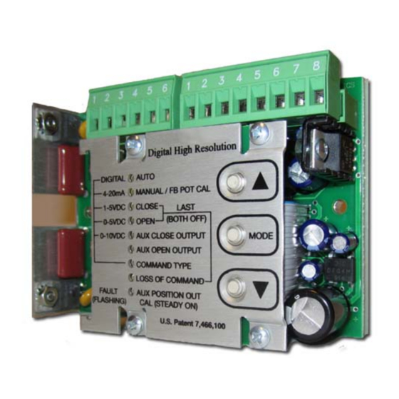
Flomatic Smart Card
Model FDHC-100 (Digital High-Resolution Controller)
Configuration and Operation Manual
AUTO
The AUTO function is the normal mode of operation for the FDHC-100; all the other functions are used to
set up the unit. While in AUTO, the unit can be controlled by various external signals, some of which can
be selected by the COMMAND INPUT function. When the unit is not in the AUTO mode, all external
controls described below will be disabled.
open
closed
Once the
and
actuator according to the command input signal. For an input signal of 0V (for 0-5V or 0-10V input), 1V
(for 1-5V input), 4.0 mA (for 4-20mA input), or 0% (for a digital input), the FDHC-100 will position the
closed
actuator to the
position as set by the user. Conversely, an input of 10V, 5V, 20mA, or 100% will
position the actuator to the defined
When the FDHC-100 is configured to use a 0-5V, 0-10V, 1-5V, or 4-20mA command, the command signal
should be connected to the appropriate pin on J2 – note that the unused input pin must be left
unconnected. When the FDHC-100 is configured for a Digital command type, an appropriate
communications option module must be installed. A communications module may be installed when
using one of the analog command types and can be used to override the analog command. The AUTO
indicator will flash whenever the unit is being controlled by the communications module.
MANUAL/FB POT CAL
The MANUAL/FB POT CAL function allows manual operation of the actuator by using the adjust buttons
(▲) and (▼) without affecting any other settings within the FDHC-100. When the (▲) button is pressed,
the motor winding connected to J1-1 is turned on while the (▼) button turns on the J1-3 winding.
Whether the actuator moves toward the
connected to J1-1 and J1-3.
The POT CAL feature provides an indication of the feedback potentiometer's setting. When the
MANUAL/POT CAL function is selected, the Manual/Pot Cal indicator will turn on - it may flash or be on
steady, depending on the actuator position. The indicator will be on steady whenever the FDHC-100
detects that the feedback potentiometer is at midrange of its rotation. As the actuator moves, causing
the feedback potentiometer to move away from midrange, the indicator will begin to flash, and the
indicator will flash at a decreasingly slower rate as the actuator moves further away from midrange.
By using the adjust buttons to position the actuator to mid-stroke (half way point between the desired
open
closed
and
positions), the feedback potentiometer can then be adjusted until a steady light occurs.
This insures that the feedback potentiometer has maximum range to reach the
positions.
CLOSE
The CLOSE function is used to set the desired
potentiometer should be checked for optimum position (see MANUAL/POT CAL), and the limit switches
should be set outside of the operating range (see STALL DETECTION FEATURE). In the CLOSE function,
the adjust buttons are used to set the actuator to any desired position, and upon pressing the MODE
button (to select the next function, OPEN), the FDHC-100 will retain the setting as the defined
position. Upon selecting the CLOSE function, the FDHC-100 will begin moving the actuator to the
Flomatic Corporation
Glens Falls, NY 12801
Phone (518) 761-9797
Fax (518) 761-9798
TM
positions have been set, the AUTO mode will control the position of the
open
position.
open
closed
or
closed
FDHC-100 Configuration & Operation Man. Rev 0
August 16, 2010
position depends on which motor winding is
position; however, prior to doing this, the feedback
6 of 14
open
closed
and
closed