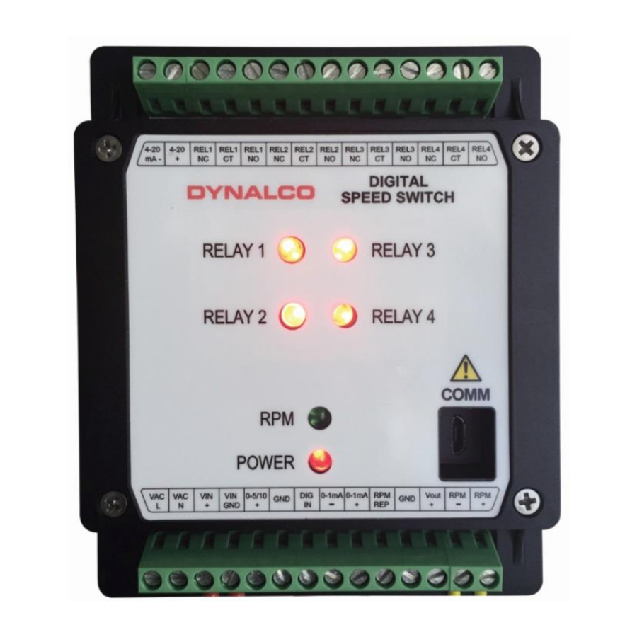
Barksdale Dynalco SST7200 Manuale di installazione e funzionamento - Pagina 4
Sfoglia online o scarica il pdf Manuale di installazione e funzionamento per Interruttore Barksdale Dynalco SST7200. Barksdale Dynalco SST7200 19. Speed switch / transmitter

Specifications
1) INPUT SUPPLY VOLTAGE:
2) FREQUENCY INPUT:
a. Input Signal Frequency Range:
b. Waveforms:
c. Input Signal Sensitivity:
d. Input Impedance:
e. CSA Approved Dynalco Sensors:
3) DIGITAL INPUT (1):
4) OUTPUTS:
a. Meter Output:
b. Proportional Output:
c. Supply Output:
d. Repeater Output:
e. Response Time:
f.
Linearity:
g. Stability:
10 - 36 VDC, maximum 10 W
0 – 50 KHz
Accepts sinusoidal or square wave (positive or zero-
crossing)
25 mV to 1.0 VRMS (selectable), Maximum allowed is
50 VRMS
10 K (minimum)
M201, M202, M231, M233, M203, M204, M205, M928
M928-24 & M951
Dry contact closure for resetting latched relay
0 – 1 mA meter output for loads up to 750 ohms
Proportional to input frequency range, configurable as:
i. 4 – 20 mA into maximum 1K load
And one of either:
ii. 0 – 5 VDC into 20K load or higher or
iii. 0 – 10VDC into 20K load or higher
Note that the 4 – 20 mA output is isolated but the 0 – 5
VDC & 0 – 10 VDC outputs are referenced to input
supply ground. 0 – 1mA output is referenced to
separate ground (Meter Output).
Regulated +12 VDC ±5%; 40 mA for active pickup
power.
Square wave 12 V peak-to-peak, 10 mA max load,
Zero based, positive going.
50 milliseconds, 10% to 90% rise (standard)
Full-scale
frequency ranges
proportionally slower.
10milliseconds, 10% to 96% rise (standard)
Full-scale
frequency
proportionally slower. For 10mSec response time the
input frequency signal must be noise free.
0.1% of full-scale (0.05%, typical) all outputs
Less than 0.05% of full-scale change with a 10%
change in supply voltage. Temperature coefficient
±0.01% per °F (±0.018% per °C)
3
below
80
Hz
ranges
below
300Hz
are
are
