Barksdale T2X Manuale di istruzioni per l'uso - Pagina 7
Sfoglia online o scarica il pdf Manuale di istruzioni per l'uso per Interruttore Barksdale T2X. Barksdale T2X 8. Mechanical temperature switches
Adjustment knob under cover
Ground screw
46 (1.81)
(internal)
28.6 (1.13)
½" NPT conduit
Mounting holes
connection
ø7.1 x 2
Terminal strip for
14.3
three connections
(0.56)
25.4 mm (1.0 inch) min.
required to remove the cover.
Contacts: color code and function
Contacts
C
= Common
= purple
NC
= Normally
= blue
Closed
Contact
NO
= Normally
= red
Open Contact
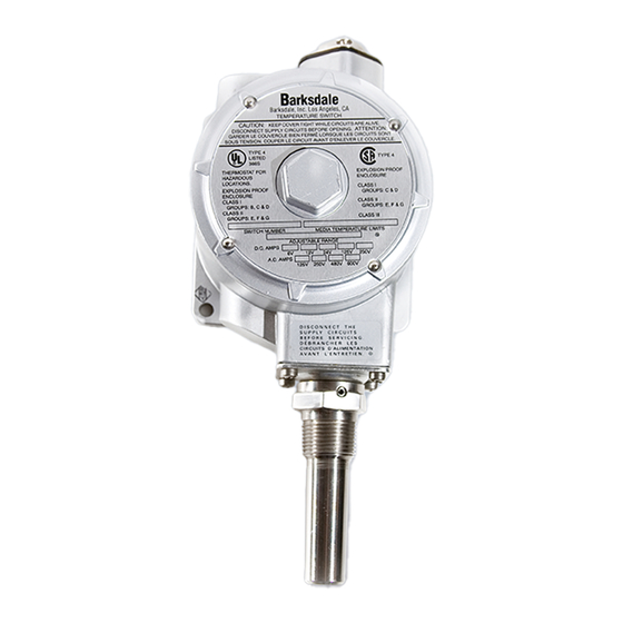
Fig. 8: Temperature switch type T1X-.../T1X-EX...
10
Adjustment knob under cover
136 (5.35)
*
36.5 (1.44)
**
51
(2.008)
ø4.75 (0.11)
6.4
Terminal strip for
(0.25)
ø2.4 (0.09)
three connections
ø4.75
(0.11)
ø2.4
(0.09)
25.4 mm (1.0 inch) min.
* ¾" NPT conduit
required to remove the cover.
connection
** Ground screw
(internal)
Contacts: color code and function
Lower contacts
Upper contacts
C
= Common
= purple
C
NC
= Normally
= blue
NC
Closed
Contact
NO
= Normally
= red
NO
Open Contact
Fig. 9:Temperature switch type T2X-.../T2X-EX...
Buy: www.ValinOnline.com | Phone 844-385-3099 | Email: [email protected]
IMPORTANT
Adjustment of several set points is performed for each set point as specified above.
Mounting holes
ø7.1 x 2
Due to the sluggishness of the capillary system switching delays may occur in case of rapid
temperature changes (>2 °C/Minute).
ø9.6
(0.38)
Wiring Code for all Types (Contact status at atm. pressure)
NC
NC
Fig. 5
Wiring Code
Use in Hazardous Locations
The weather-proof standard temperature switches must not be used for hazardous locations.
Special temperature switch types; T1X-EX, T2X-EX and L1X-EX for Ex d IIC T6 explosion-proof
applications with Certificate No. ISSeP 08 ATEX 024X.
These special models are suitable for gas and dust applications and approved for Ex II G D in
= brown
accordance with the ATEX 94/9/EC regulations.
= orange
These special switches with explosion-proof enclosure must be wired with Ex Certified conduit
connection, or cable gland. The switches may only be used in accordance with the instructions and
= yellow
provisions of the declaration of conformity.
Power circuit 1
1
C
NO
C = purple
NC = blue
2
NO = red
C
Circuit 1 = lower contact (low)
NO
Circuit 2 = upper contact (high)
Power circuit 2
C = brown
NC = orange
NO = black
7