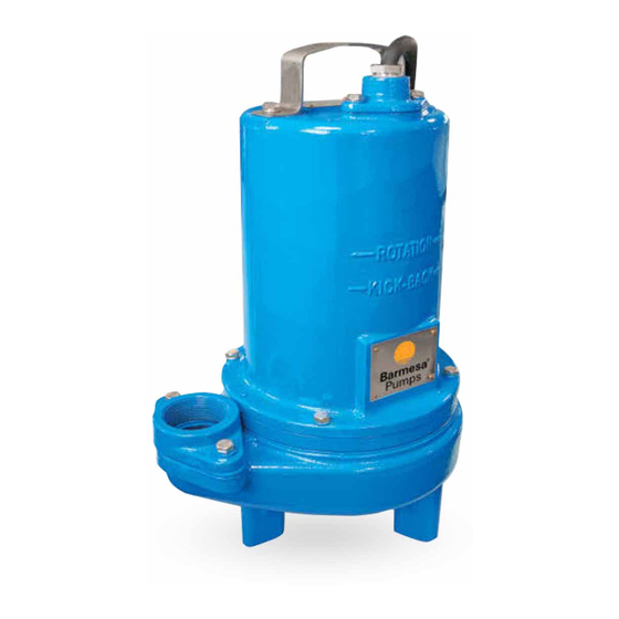
Barmesa Pumps 2BSE74SS Manuale di installazione, funzionamento e manutenzione - Pagina 12
Sfoglia online o scarica il pdf Manuale di installazione, funzionamento e manutenzione per Pompa dell'acqua Barmesa Pumps 2BSE74SS. Barmesa Pumps 2BSE74SS 13. Submersible solids handling pumps
Anche per Barmesa Pumps 2BSE74SS: Manuale di installazione, funzionamento e manutenzione (13 pagine)

SYMPTOM
D) Pump delivers insufficient
capacity.
E) The pump turns on and off
very frequently (more than
usual).
barmesa.com
F) The pump goes off and on
regardless of the switch and
activates the thermal overload
protector . CAUTION!, the
pump may start unexpectedly.
Disconnect power supply.
G) Pump operates noisily or
vibrates excessively.
NOTE: Barmesa Pumps assumes no responsibility for damage or injury due to disassembly in the field. Disassembly of the pumps or supplied accessories other
than at Barmesa Pumps or its authorized service centers, automatically voids warranty.
POSSIBLE CAUSE
Incorrect low voltage.
Discharge restricted.
Check valve is partially
closed or installed
backward.
Shut-off valve closed.
The impeller is jammed or
the shaft is loose, worn or
damaged, or inlet
(10)
plugged.
Pump may be air locked
casuing pump not to flow.
(11)
Pumprunning backwards.
(12)
Check valve is partially
closed or installed
backward.
fixtures are leaking.
(13)
Groundwater is entering
(17)
basin.
Wiring or electrical current
is inappropriate.
The total dynamic charge
is below the
recommended minimum.
Impeller is jammed or
bounds near the pump
(10)
body.
Excessive water
temperature (internal
(14)
protection only).
Worn bearings, the motor
shaft bent.
Obstruction in the cavity
of the impeller or is
(10)
impaired.
Impeller rotation is
(12)
incorrect.
Piping attachments to
build dtructure too loose
(15)
or rigid.
CORRECTIVE ACTION
(1)
(9) Open the valve.
(7)
(8)
(10) Check the impeller so that it rotates freely. Clean
the cavity of the impeller and the suction of the pump
body by removing any obstructions.
(9)
(11) Loosen union slightly to allow trapped air to
escape. Verify that turn-off level of switch is set so
that the suction is always flooded. Clean vent hole.
(12) Check rotation. If power supply is three phase,
reverse any two of three power supply leads to
ensure proper impeller rotation.
(13) Repair fixtures as required to eliminate leakage.
(14) Check the temperature of the liquid to be
(8)
pumped, which must not exceed 160 ° F ( 71 ° C).
(15) Replace portion of discharge pipe with flexible
connector or tighten existing piping..
(16) Turn to automatic position.
(17) Check for leaks around basin inlet and outlets.
(1)
(6)
(4)
Troubleshooting Chart
12
