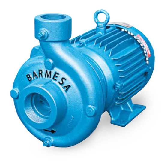
Barmesa Pumps 62070044 Manuale di installazione, funzionamento e manutenzione - Pagina 8
Sfoglia online o scarica il pdf Manuale di installazione, funzionamento e manutenzione per Pompa dell'acqua Barmesa Pumps 62070044. Barmesa Pumps 62070044 16.

4Starting
When starting for the first time your
equipment check that the discharge
valve is 90% closed. Gradually open
the valve until the motor runs at full
load (amperage plate). Never allow
the amperage consumed by the
pump
exceeds
permitted by the engine.
4Mechanical seal
Mechanical seals installed in this
pumps are lubricated by water, there
for the pump should not be operated
dry. You will find the appropriate seal
for each use and liquid to be
pumped, check with your Barmesa
Pumps
distributor
information.
IMPORTANT!
unplug the pump before
applying
service or repair to avoid
barmesa.com
electric shock.
4Maintenance
Body and Impeller - All pump parts
are removable by removing nuts and
bolts.
For
body
disconnect
the
discharge, and remove the body of
the
intermediate
maintenance of the impeller is not
necessary to remove the suction or
discharge, simply remove the body
nuts; this would uncover the impeller.
Examine and replace if it shows wear
or damage.
When
the
impeller
replacement, remove the screw of
the shaft, and using a puller, remove
the impeller being careful not to
abuse the keyway of the shaft.
It is important not to overfill the oil
tank because it would cause an
increase in pressure by heating,
affecting the bearings and seals. In
normal
operation,
temperature increases 122 °F above
ambient temperature.
Mechanical Seal - To inspect or
replace the shaft seal, remove the
body and impeller. If any part shows
wear or damage, replace both parts
(stationary seat and rotary part). The
rotating seal parts may be stuck
together with the shaft, this happens
the
maximum
when the seal has been assembled
for a long time.
If the mechanical seal does not leak
and there is need to open the pump
for inspection or cleaning, DO NOT
remove the seal, remove the spring
only if the impeller needs to be
removed. Once a seal has been in
for
more
operation is very difficult to remove
and reassembly without creating a
seal leak.
-
Always
4Disassembly
maintenance,
Mechanical Seal - Perform the steps
above. Remove the rotating part. It
may be necessary to remove the
intermediate link to remove the
stationary seat. To do this, remove the
nuts and washers that attach the
coupling
maintenance,
removing the coupling, the steady
suction
and
part will move towards the front seat
of the shaft and the sleeve. If the seat
coupling.
For
does not yield itself, push from the
rear of the coupling.
requires
4Reassembly
Mechanical Seal - Identify all parts of
Figures 7 and 8. The ring (6) and seat
(1) are perfectly polished, so care
must be taken not to scratch or
smudge. The cleaning during the
assembly process is very important.
the
frame
to
the
motor.
When
Handle seal parts with
extreme care. DO NOT
damage lapped surfaces.
IMPORTANT! - All parts
must
be
clean
before
reassembly.
Operation & Maintenance
Step 1: Install the intermediate
coupling
if
it
was
removed. Make sure the shaft and
cavities, where will it seats, are clean.
The shaft sleeve should not be sharp,
but a radius of about 1/32". It is
recommended that lightly polish the
area of the shaft. If the shaft and it
radius are perfectly polished, the seal
can be relatively easily installed.
Step 2: Install the seat assembly (1
and 2) on the inside of the
intermediate
coupling,
moistening with water on the rubber
parts (do not use grease or oil). This
assembly should be done only
manually, meaning without the use
of an instrument.
Step 3: Install the rotating portion of
the seal without the spring. Moisten
the arrow and the inside of the seal
with some water (do not use grease
or oil). With clean, dry hands, insert
the rotating portion to the shaft,
sliding it abuts the stationary seat.
Once the seal is in place, insert the
spring (5).
Step 4: Place the impeller and
washers; tighten the hex screw.
previously
slightly
7
