Barnstead Thermolyne Corporation 801 Series Manuale operativo ed elenco parti - Pagina 10
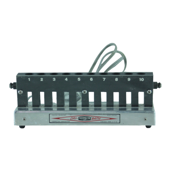
Sfoglia online o scarica il pdf Manuale operativo ed elenco parti per Accessories Barnstead Thermolyne Corporation 801 Series. Barnstead Thermolyne Corporation 801 Series 16. Dri-bath test tube incubator
M
S
AINTENANCE AND
Caution
Grip thermistor on sleeving near alu-
minum plate.
10
ERVICING
13. Connect the element leads. Replace the cover
and screws.
14. Place the unit upright. Calibrate the unit accord-
ing to the "Calibration" section of this manual.
Replacing the PC Board
1.
Disconnect from line voltage.
2.
Place unit upside down.
3.
Remove the four screws on the outside of the
lower casting. Remove bottom cover.
4.
Disconnect all terminals from PC Board.
5.
Carefully remove thermistor from block.
6.
Remove PC board from clips.
7.
Install new PC board. Reconnect line cord leads
terminals marked L1 & L2 - white or blue on L2,
black or brown on L1. Reconnect element leads.
8.
Clean the old (RTV) silicone from the plate.
9.
Using 100% silicone, coat the tip of the thermis-
tor. Reinstall the thermistor in the block.
10. Replace the cover and screws.
11. Place the unit upright. Recalibrate the unit
according to the "Calibration" section of this
manual.