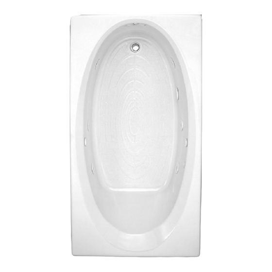
American Standard Renaissance 6060V Manuale di installazione e funzionamento - Pagina 12
Sfoglia online o scarica il pdf Manuale di installazione e funzionamento per Vasche da bagno American Standard Renaissance 6060V. American Standard Renaissance 6060V 17. Lifetime / evolution and renaissance whirlpools and bathtubs
Anche per American Standard Renaissance 6060V: Manuale di installazione (15 pagine)

- 1. Thank You
- 2. Table of Contents
- 3. Safety Instructions
- 4. General Information
- 5. Optional Components
- 6. Specifications
- 7. Roughing-In Reference
- 8. Roughing-In Reference
- 9. Framing and Support Instructions
- 10. Mounting Instructions
- 11. Electrical Connections
- 12. 6060L/V Corner EZ-Install Heater
- 13. Operation
- 14. Drain Connection and System Test
- 15. Care and Cleaning
- 16. Warranty
WHIRLPOOL ELECTRICAL INSTALLATION INSTRUCTIONS
All wiring must be performed by a licensed electrician in accordance with the national electrical code and all other applicable codes.
WARNING: When using electrical products, basic precautions should always be observed, including the following:
!
1. DANGER: RISK OF ELECTRIC SHOCK! Connect only to a circuit protected by a ground-fault circuit interrupter.
2. Grounding is required. The unit should be installed by a licensed electrician and grounded.
3. Permit access for servicing motor as noted.
4. All building materials and wiring should be routed away from the pump body and heater (if equipped).
PLEASE SEE THE FOLLOWING TABLE FOR GFCI CIRCUIT REQUIREMENTS:
GFCI CIRCUIT REQUIREMENTS:
The whirlpool should be installed on a 120 vac,
GFCI circuit.
The circuit should be hard-wired from the electrical power supply panel. The
circuit must be a three (3) wire circuit from the electrical supply panel. A
grounded neutral wire and a third wire, earth ground, are essential.
Optional heater requires a separate 15 amp maximum GFCI circuit.
W IRE SEL E C T I O N G U I D E
W ire L e n gt h
Wire Size ( A W G )
753737-100 Rev. E
15
20
12 0 VA C
G N D .
READ AND FOLLOW ALL INSTRUCTIONS
Ma x i m u m d ista n ce fro m
f u s eb o x to m otor
5 0 '
10 0 '
1 50 '
1 15 V Po we r Li ne
1 2
1 0
12
FOR MODEL NUMBERS:
amp dedicated
amp dedicated
PUMP/MOTOR
ELECTRICAL DIAGRAM
c hart a re re comm endat i ons
20 0'
8
8
2422, 2425, 2645, 2732
2771, 2908
ALL MODELS
6060, 2775, 2773, 2711,
2774, 7236
ALL MODELS
Th e s ize s s hown on t his
for copp er co nduct or s
only. Alway s follo w
l oca l a nd nati onal
e lec trica l c odes
