Ekinex EK-ET2-TP Manuale di avvio rapido - Pagina 2
Sfoglia online o scarica il pdf Manuale di avvio rapido per Controllore Ekinex EK-ET2-TP. Ekinex EK-ET2-TP 8. Room temperature controller with humidity and co2 equivalent regulator

Plate
Type
Appearance
code *
EK-PQS-...
1-fold **
\
EK-PRS-...
1-fold **
EK-P2G-...
2-fold ***
EK-P2S-...
2-fold ***
(*) To be completed with the extension for colour, material and finishing
(**) For mounting without frame ('NF) it requires the EK-TAQ adapter
(***) For mounting without frame ('NF) it requires the EK-A71-... adapter
Frame
The room temperature controller can be completed by a
square 1-fold frame or by a rectangular 2-fold frame of the
flank or form series. The 'NF (No Frame) versions of the
pushbutton do not require any frame.
Mounting
The device has degree of protection IP20, and is therefo-
re suitable for use in dry interior rooms. The installation of
the device requires the following steps:
Mounting with frame, round flush-mounting box
Carry out the following steps:
• fix the metallic support (h) with the screws (g) on a
flush-mounting box (i) provided with suitable fixing ho-
les;
• snap a square frame (f) of the form or flank series, in-
serting it from the rear of the preassembled thermostat-
adapter (d+e);
• insert the bus terminal, previously connected to the bus
cable, in its slot on the rear side (see also: "Connection
of the KNX bus line"). At this point it is recommended
to carry out the commissioning of the pushbutton (see
also "Configuration and commissioning") or at least the
download of the physical address;
a
b
c
d
Mounting with frame
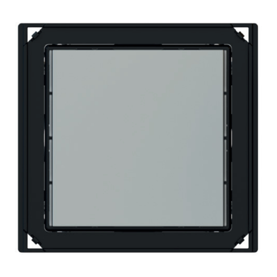
a) 1-fold plate (square, with 60 x 60 mm window)
b) Rocker
c) Screws (for device)
d) Device
e) Adapter (delivered preassembled on the device)
f) Frame (square, form or flank series)
g) Screws (for metallic support)
h) Metallic support
i) Flush-mounting box (not delivered by ekinex
Window
modularity [mm]
60 x 60
60 x 60
55 x 55 (1)
60 x 60 (1)
60 x 60 (2)
e
g
f
h
i
)
®
• insert thermostat and adapter (d+e), completed with
the frame (f), in the metallic support (h). Mounting the
pushbutton follow the indication TOP (arrow tip pointing
up) on the rear side of the device;
• tighten thermostat, adapter and frame (d+e+f) on the
metallic support (h) with the two screws (c);
• snap the plate (a);
• snap the rocker (b) to complete the installation.
Mounting with no frame, round flush-mounting box
Carry out the following steps:
• insert the metallic support (f) on the adapter (g);
• fix adapter and metallic support (f+g) with the screws
(e) on a flush-mounting box (h) provided with suitable
fixing holes;
• insert the bus terminal, previously connected to the bus
cable, in its slot on the rear side (see also: "Connection
of the KNX bus line"). At this point it is recommended
to carry out the commissioning of the pushbutton (see
also "Configuration and commissioning") or at least the
download of the physical address;
• insert the thermostat (d) in the support-adapter (f+g).
Mounting the device follow the indication TOP (arrow
tip pointing up) on the rear side of the device;
• tighten the device on the support-adapter (f+g) with the
two screws (c);
• snap the plate (a);
• snap the rocker (b) to complete the installation.
a
b
c
Mounting with no frame
a) 1-fold plate (square, with 60 x 60 mm window)
b) Rocker
c) Screws (for device)
d) Device
e) Screws (for metallic support)
f) Metallic support
g) Adapter for 'NF series (delivered with the device)
h) Flush-mounting box (not delivered by ekinex
Mounting with rectangular flush-mounting box
Carry out the following steps:
• insert the metallic support (f) on the adapter (g);
• for versions provided with frame only: snap a rectangu-
lare frame (f) of either form or flank series, starting from
the back side of the support-adapter group (f+g) ;
• fix adapter and metallic support (f+g) (and eventually
the frame, h) with the screws (e) on a flush-mounting
box (i) provided with suitable fixing holes;
• insert the bus terminal, previously connected to the bus
cable, in its slot on the rear side (see also: "Connection
of the KNX bus line"). At this point it is recommended
to carry out the commissioning of the pushbutton (see
also "Configuration and commissioning") or at least the
download of the physical address;
• insert the thermostat (d) in the support-adapter (f+g).
Mounting the device follow the indication TOP (arrow
tip pointing up) on the rear side of the device;
• tighten the device on the support-adapter (f+g) with the
2
d
e
min 0,3 m
f
g
)
®
h
