Ekinex EK-HH1-TP Manuale - Pagina 2
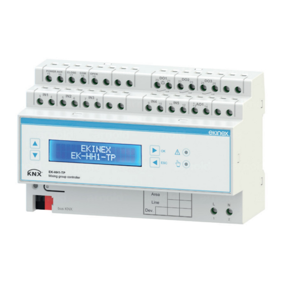
Sfoglia online o scarica il pdf Manuale per Controllore Ekinex EK-HH1-TP. Ekinex EK-HH1-TP 4. Controller for mixing group

Terminal blocks for connection of inputs and outputs
POWER AUX
CLOSE
COM
OPEN
15
16
17
18
19
IN1
IN2
IN3
3
4
5
6
7
8
Nr.
Marks
Connection
3-4
IN1
Input 1 (delivery temperature sensor)
5-6
IN2
Input 2 (return temperature sensor)
7-8
IN3
Input 3 (external temperature sensor)
9-10
IN4
Input 4 (configurable as AI or DI)
11-12
IN5
Input 5 (configurable as AI or DI)
13-14
AO1
0...10 V servomotor control output
15-16
POWER AUX
TRIAC power supply (230 Vac or 24 Vac)
17
CLOSE
Servomotor control output (closing)
18
COM
Servomotor control output (common)
19
OPEN
Servomotor control output (opening)
20-21
DO1
Relay output for circulating pump
22-23
DO2
Relay output (additional functions)
24-25
DO3
Relay output (additional functions)
Lower part of the casing
POWER AUX
CLOSE
COM
OPEN
15
16
17
18
19
IN1
IN2
IN3
3
4
5
6
7
8
EK-HH1-TP
Mixing group controller
bus KNX
1
2
3
1) Programming pushbutton
2) Terminal block for KNX bus line
3) Programming LED
4) Field for physical address
5) Terminal blocks (1, 2) for 230 Vac power supply
Membrane keyboard and display
6
EK-HH1-TP
Mixing group controller
8
7
6) Pushbutton for scrolling menu up
7) Pushbutton for scrolling menu down
8) Backlighted alphanumeric display 16 columns x 2 rows
9) Pushbutton "back"
10) Manual mode LED
11) Alarm LED
12) Pushbutton "confirm"
DO1
DO2
DO3
20
21
22
23
24
25
+
-
IN4
IN5
AO1
9
10
11
12
13
14
DO1
DO2
DO3
20
21
22
23
24
25
+
-
IN4
IN5
AO1
9
10
11
12
13
14
OK
ESC
Area
L
N
Line
Dev.
1
2
4
5
12
11
OK
ESC
10
9
Mounting
The device has degree of protection IP20, and is there-
fore suitable for use in dry interior rooms. The housing
is made for rail mounting according to EN 60715 in bo-
ards or cabinets for electrical distribution. The correct
mounting is when the KNX bus terminal is located at the
bottom. When installing be sure to leave accessible only
the front panel; all other sides must not be accessible. For
the mounting proceed as follows:
• with the aid of a tool bring the locking device in the
fully lowered position (a);
• place the upper edge of the rear inner profile on the
upper edge of the rail (b);
• rotate the device towards the rail (c);
• push the locking device upward until it stops (d).
!
Warning! When the device is installed in the boiler
room, make sure it is accessible only the membra-
ne keyboard and that the connections are properly
protected against the ingress of dust or liquids.
1
3
Before removing the device, be sure that inputs, outputs,
power supply have been disconnected and the bus ter-
minal has been extracted from its slot. Use a screwdriver
to slide down the locking device and remove the device
from the rail.
Connection of the KNX bus line
The connection of the KNX bus line is made with the ter-
minal block included in delivery and inserted into the slot
at the left bottom of the housing.
Characteristics of the KNX terminal block
• spring clamping of conductors
• 4 seats for conductors for each polarity
• terminal suitable for KNX bus cable with single-wire
conductors and diameter between 0.6 and 0.8 mm
• recommended wire stripping approx. 5 mm
• color codification: red = + (positive) bus conductor,
black = – (negative) bus conductor
!
Warning! In order to supply the KNX bus lines use
only a KNX bus power supply (e.g. ekinex EK-AB1-
TP or EK-AG1-TP). The use of other power supplies
can compromise the communication and damage
the devices connected to the bus.
2
2
4
