American Time SiteSync IQ Manuale di installazione e funzionamento - Pagina 5

Sfoglia online o scarica il pdf Manuale di installazione e funzionamento per Trasmettitore American Time SiteSync IQ. American Time SiteSync IQ 13. Wireless system controller with standard gps & magnetic mount tx antenna
Anche per American Time SiteSync IQ: Manuale di installazione rapida (2 pagine), Manuale di installazione e funzionamento (2 pagine), Manuale di installazione e funzionamento (7 pagine), Manuale di installazione e funzionamento (6 pagine), Manuale di installazione rapida (2 pagine), Manuale di installazione rapida (2 pagine), Manuale di installazione rapida (2 pagine), Manuale di installazione rapida (2 pagine), Manuale di installazione rapida (2 pagine), Manuale di installazione rapida (2 pagine), Manuale di avvio rapido (2 pagine), Manuale di avvio rapido (2 pagine), Manuale di avvio rapido (2 pagine)
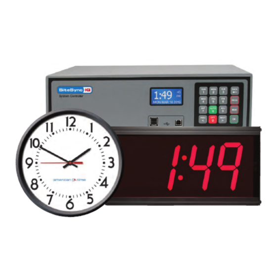
American Time SiteSync IQ Manuale di installazione e funzionamento
SiteSync IQ Wireless Controller
Installation Manual
Mounting the SiteSync IQ Wireless Controller
The SiteSync IQ Wireless Controller should be:
• Located indoors in a dry location
• Mounted upright on a vertical surface
• Protected from physical damage
• Protected from water, including condensation
• Out of direct sunlight
• Operated by trained personnel
An area at least 24" wide x 24" high should be reserved to allow a clearance of at least 12" below and on the left side of the
SiteSync IQ Wireless Controller. Wiring for power, clock and signal circuits must enter through conduit knockouts along the
bottom of the enclosure. Connection for the tone output is located on the left side.
The SiteSync IQ Wireless Controller is designed to be wall-mounted by a molded hanger
and screws. Appendix A shows a diagram for locating wall hangers at the appropriate
spacings to mate with the unit.
Electrical Connections
WARNING
To prevent electrical shock, do not apply electrical power to the SiteSync IQ Wireless Controller, clock relays or signal
relays before completing all wiring connections.
120vac Supply Connections
120vac supply connections are located on the block of three (3) screw terminals located center left inside the wiring
compartment. The hot terminal is located at the far left position of this block of three. The neutral terminal is located at the center
position of this block of three. The ground terminal is located on the right side of this block of three.
Fuse
A 2 amp - 250vac fuse protects the power input circuit. Each clock and signal relay circuit is protected by an 8 amp - 250vac
fuse.
WARNING
To protect against shorts between power and signal circuits, all wires connected to the power, clock, and signal circuit
terminals must be insulated to 300vac.
Clock Connections
CAUTION
To prevent damage to relays, relay contact voltage must not exceed 240vac.
Appendix B shows wiring connections to the SiteSync IQ Wireless Controller and secondary clocks for all clock types controlled by
the SiteSync IQ Wireless Controller.
Signal Circuit Connections
CAUTION
To prevent damage to relays, relay contact voltage must not exceed 240vac.
Terminals for connecting to the normally open and common contacts of the optional signal circuit relays are located in the wiring
compartment at the bottom of the enclosure.
© American Time
Controller Installation
24"
At least 12"
24"
Wall
Manual On
System On
5