Door Controls DC10327 Manuale - Pagina 2
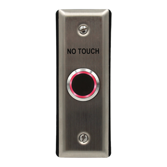
Sfoglia online o scarica il pdf Manuale per Sistema di apertura della porta Door Controls DC10327. Door Controls DC10327 4. Outdoor no-touch wave sensor

Specifications:
Power
Current
Standby
Drain
Triggered
(max.)
Relay Type
Response Time
LEDs
Standby
Triggered
Output Time
Range
IP Rating
Temperature Range
Color function reversible when properly installed.
Installation:
1. Run four wires through the wall to the jamb mount box provided.
2. Connect the four wires from the back box to the wave sensor according the Wiring Diagram.
3. For weatherproof installation, use a waterproof back box and apply a bead of silicone sealant (not
included) around the rim of the back box and faceplate edge. Apply a small amount of sealant below
each screw head.
4. Screw the plate into the back box, taking care not to crimp the wires and ensuring a good seal.
5. Remove clear protective film from the sensor before use.
WARNING: Do not connect any device that will exceed 1.2A@24VDC.
Changing the LED Color Jumper Placement:
Jamb Mount Models
Adjusting the Sensor Range and Trigger Time:
1. The sensor range can be adjusted from 2"~7" (5~18 cm).
2. The trigger time can be adjustment trimpots to turn.
NOTE: Do not force the adjustment trimpots to turn. Only
minimal force is needed.
Trigger time: 0.8~30 seconds, toggle*
Default: 0.8 seconds
*Toggle: turn all the way clockwise
Sensor range: 2"~7" (5~18 cm)
Default: 7" (18cm)
321 VZ County Road 4500 · Ben Wheeler, TX 75754 · 800.437.3667 · DoorControlsUSA.com
12-24 VDC
16mA@12VDC / 25mA@24VDC
25mA@12VDC / 32mA@24VDC
SPDT dry contact, 1.2A@24VDC
10ms
Red
†
Green
†
0.8~30 s, toggle
2"~7" (5~18cm)
IP65
†
-4°~131° F (-20° ~55° C)
*Set trigger time to maximum for toggle
