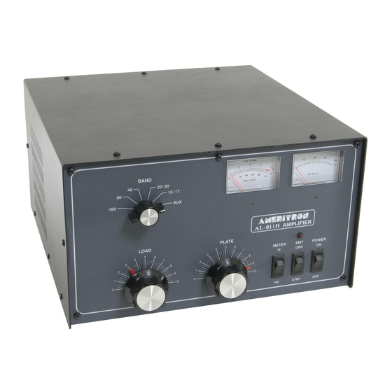
AMERITRON AL-811H Manuale d'uso - Pagina 2
Sfoglia online o scarica il pdf Manuale d'uso per Amplificatore AMERITRON AL-811H. AMERITRON AL-811H 19. Hf power linear amplifier
Anche per AMERITRON AL-811H: Manuale di istruzioni (12 pagine), Istruzioni per il disimballaggio Manuale (11 pagine), Manuale (13 pagine)

marginally stable. It should really have a 200-ohm cathode swamping resistor, our kit PN 811R200K. This kit has
one chassis mount RF-rated 25W resistor, one 0.01uF capacitor, and hardware. In addition you will need a 0.113
to 0.125" (1/8") drill to add one hole for 4-40 machine screw clearance.
AL811H
The four tube model is neutralized. Four 811 tubes, regardless of layout, become unstable someplace above 15
meters and behave poorly on ten and fifteen meters when not neutralized. Any swamping resistance is optional;
it just makes neutralization less critical and closer matches drive level to 100W exciters. With bias changes the
swamping is not required.
NOTE: I find many amplifiers that have NOT been properly neutralized from the factory. This is not from a variation
in tubes. The only time tubes might require neutralization is when 572B's are swapped in. To equipment operators,
poor neutralization is most easily noticed by a fairly large 10 meter input SWR variation as the amplifier is tuned.
A second neutralization indicator is exciter power varying as the amplifier is tuned past 10M grid current peak.
A third and by far least dependable identification method is by plate current dip not coinciding with maximum
output.
Neutralization
I neutralize 811's by activating the relay system with an external low voltage dc supply of about 18 volts
positive applied to where meter lamp positives connect. The antenna relays are activated by grounding the
RLY jack. Feed an antenna analyzer into the RF input or output jacks, and listen with a radio on the other port.
With the amplifier on 10 or 15 meters adjust the analyzer and receiver to the same frequency. Adjust the
PLATE and LOAD for maximum signal. Now you can safely vary flapper plate positioning for minimum signal
level. The best flapper setting is the compromise between 10 and 15M nulls, with 10M having priority.
Major Concerns
There have been dozens of instances of hard faults in tubes damaging radios. This has been blamed on many
things by many people, including ALC and relay lines. The actual damage is from tube arcs from gas or debris in
tubes. The damage comes from the tube arc energy making it out the RADIO coax connector, through that coax,
and into the radio. I'm 100% positive of this! While this happens infrequently, the damage can be catastrophic to
the radio.
Tube arcs range from minor flashovers that clear the fault low energy to hard solid faults that dump full high
voltage on the tube cathode and grid. In light faults, with a directly grounded grid, the grid is able to divert most of
the arc energy harmlessly to ground. Only the most sensitive radios are damaged by these arcs.
With hard faults an ionized path occurs through and around the grid. This transfers a great deal of energy to the
tube filament. These arcs are devastating to components, including the radio. These hard anode-to-filament arcs
produce a very sharp rise high voltage spike on the filament. The filament, if unprotected, reaches well over 1000
volts in microseconds. This arc is very much like a miniature lightning surge. The filament choke has significant
common mode series impedance. Along with bypass capacitors this forms a low-pass, only passing arc frequencies
below ~100 kHz through the filament winding to the bias and relay circuit. It takes a very hard sustained arc to
damage this path.
The second more troublesome path is through parallel 0.01 uF filament coupling capacitors to the tuned input. The
tuned input circuit, being a low-pass, rings. This stretches the pulse out into a several mS long series of lower-level
oscillations below the band selected. The pulse can then make it through the tuned input much like a brief high
power transmitter of a few hundred watts into the radio. Worst case peak voltage level is an arc while on ten
meters, while worst case pulse length is on 160 meters.
