AMERITRON ARI-500 Manuale di istruzioni - Pagina 4
Sfoglia online o scarica il pdf Manuale di istruzioni per Interruttore AMERITRON ARI-500. AMERITRON ARI-500 16. Automatic band switch for the ameritron als-500m; ameritron als-600 amplifiers
Anche per AMERITRON ARI-500: Manuale di istruzioni (13 pagine)
ARI-500 Automatic Band Switch for ALS-500
Skip this section and go to interfacing ARI-500 to radio for keying and band
data, if the ALS-500RC will not be used.
The optional ALS-500RC remote head can be used with the ARI-500. The
ALS-500RC will display the current, power on, TX and O/L of the amplifier.
The following is for using the ALS-500RC Remote Head with the ARI-500:
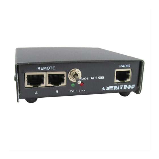
1. Connect a patch cable to Remote port A of the ARI-500.
2. Connect the other end to port A of the ALS-500RC remote.
3. Port B is not used during this application.
Note: JMP 2 inside the ARI-500 determines the function of the ALS-500RC
.
A. JMP 2 in the 1 to 2 position (Fig. A) will allow the Auto O/L Reset, and
Current Meter to work, the Power, TX and O/L indicators to operate.
The ALS-500RC's Power Switch will have to be in the on position for the
indicators to function. The power switch will not turn the amplifier off. It will
only turn the power to the remote off. Refer to the Amplifier's manual for
turning the amplifier's power off.
B. JMP 2 in the 2 to 3 position (Fig. B) will allow the Current Meter, Power,
TX and O/L indicators to function. The Auto O/L Reset will not work. The O/L
will have to be reset by switching the ALS-500RC's Power Switch off and back
to on. The ALS-500RC power switch will turn the ALS-500M's power off.
When the power is switched to on allow 4 seconds for the amplifier to turn on.
Figure A. (Factory default)
Interfacing ARI-500 to Radio for keying and Band Data
4
Instruction Manual
Figure B.