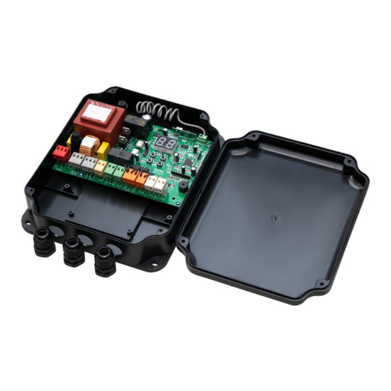
DoorHan PCB-SW Manuale di istruzioni per la programmazione - Pagina 13
Sfoglia online o scarica il pdf Manuale di istruzioni per la programmazione per Pannello di controllo DoorHan PCB-SW. DoorHan PCB-SW 20. Control board
Anche per DoorHan PCB-SW: Manuale di istruzioni per la programmazione (20 pagine)

5. Connection diagram for auxiliary lighting
To connect an auxiliary lighting, use an intermediate relay with the following technical characteristics:
power supply voltage — 24 VDC;
switching current — 10 А.
J1
5 А
M1
M2
COM OP CL
COM OP CL
COM OP CL
COM OP CL
PE N L
E N L
1 2 3 4 5 6 7 8 9 10 11
1 2 3 4 5 6 7 8 9 10 11
6. Connection diagram for traffic llights
To connect traffic lights, use an intermediate relay with the following technical characteristics:
power supply voltage — 24 VDC;
switching current — 10 А.
NOTE:
To switch on a signal terminal (S) in the traffic lights mode see the basic programming table.
J1
5 А
J7
M1
M2
COM OP CL
COM OP CL
COM OP CL
COM OP CL
LAMP S-B-S
LAMP S-B-S
PE N L
E N L
1 2 3 4 5 6 7 8 9 10 11
1 2 3 4 5 6 7 8 9 10 11
~ 220 V
50 Hz
J7
FOTO
FOTO
LAMP S-B-S
LAMP S-B-S
PED OP CL COM STOP +24V
PED OP CL COM STOP +24V
12
12
13 14 15 16 17 18 19 20 21
13 14 15 16 17 18 19 20 21
~ 220 V
50 Hz
J4
FOTO
FOTO
PED OP CL COM STOP +24V
PED OP CL COM STOP +24V
12
12
13 14 15 16 17 18 19 20 21
13 14 15 16 17 18 19 20 21
J4
J3
S Lock
S
J3
S Lock
S
24 VDC 10 A
ELECTRICAL CONNECTIONS
24 VDC 10 A
red
green
13
