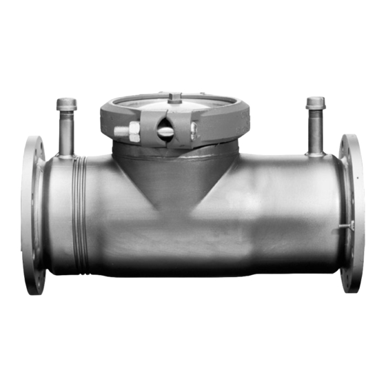
AMES 1000SS Series Manuale - Pagina 2
Sfoglia online o scarica il pdf Manuale per Unità di controllo AMES 1000SS Series. AMES 1000SS Series 4. Detector check valve assemblies sizes: 4" – 10" 100-250mm

Installation Instructions
NOTE: Ames assemblies require minimum maintenance. All
assemblies must be retested once maintenance has been
performed. Before servicing be certain shut off valves are closed.
A.
The installation and maintenance of any Ames Detector
Check Valve should be performed by a qualified licensed
technician. Failure to do so may result in a malfunctioning
assembly. All instructions should be read thoroughly by the
technician before installation or performing any maintenance
on the assembly.
B.
Before installing an Ames Detector Check Valve, flush the
lines thoroughly to remove all debris, chips and other foreign
objects. Failure to do so may make the assembly inoperable.
4" and 6" Cam-Check Removal
Removing Cam-Check
Place yourself so that the water flow through the valve is left to right.
1. Shut down water system by closing two gate valves and lock out
system if possible. Slowly open bleed port to relieve internal pressure.
After pressure is relieved, loosen bolts on groove coupler and remove
groove coupler and copper plate from valve body.
2. Unscrew (counter clockwise as viewed through the port facing the
check) the Cam-Check. Insert the two grooved coupler bolts into the
holes in the face of the seat. Be sure that the pins or bolts are
installed with one on each side of the cam bar as shown. Insert a long
screwdriver or pry bar between opposing pins and loosen the check
counter clockwise) until it comes free to turn by hand. Finish unscrew-
ing the Cam-Check by hand using the support ears for the clapper
and cam bar to turn the check. (See fig #1A)
3. Lift the Check straight up and out of the port access hole.
4" and 6" Cam-Check Installation
Install the Cam-Check
Prior to installing the Cam-Check, ensure that all threads are clean
and free of debris, grit, or other particles. Thoroughly clean O-rings
grooves and lubricate O-rings with an FDA approved lubricant.
1.
Insert the Cam-Check through the cover port with the clap-
per facing down. Align the threads of the Cam-Check with
the threads in the body and start to thread the Check in by
hand - using the ears which extend from the seat ring to
turn the check assembly. DO NOT use the clapper or the
cam bar to turn the check assembly.
2.
Tighten the Cam-Check. Insert grooved coupler bolts into
the holes in the face of the seat (or use the bolts from the lid
groove coupler). Be sure that the pins or bolts are installed
with one on each side of the cam bar. Insert a long screw
driver or pry bar between opposing pins and tighten the
check (clockwise as viewed through the port facing the
check) until it comes to a solid stop. The back the check
out about 15 degrees or from the 1:00 position to the 12:00
position. (See Fig #1B).
START UP: After re-installation of the cover plate and groove coupler — the downstream shutoff valve should be closed. Open upstream
gate slowly, fill the valve and bleed the air through bleed port. When valve is filled, open the downstream shut off slowly. Failure to bleed air
from assembly may cause water hammer or shock damage to the water system.
C. Allow sufficient clearance around the installed assembly to
conduct testing, servicing and inspection. Allow a minimum of
12" from the flood level to the bottom of the assembly.
D. Be sure to contact local code authorities for proper
installations.
INSTALLATION NOTE: The flange gasket bolts for the gate valves
should be retightened during installation as the bolts may have
loosened due to storage and shipping.
ATTENTION INSTALLER: After installation, please leave this
Instruction Sheet for occupant's information.
Figure #1A
Figure #1B
2
