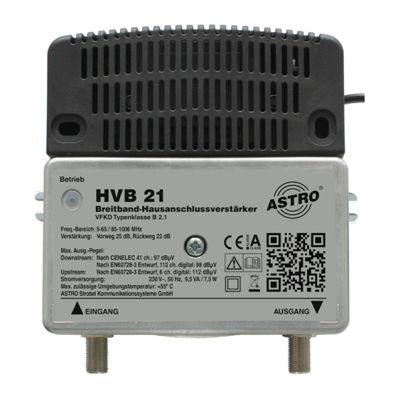
ASTRO HVB 21 Manuale operativo - Pagina 14
Sfoglia online o scarica il pdf Manuale operativo per Amplificatore ASTRO HVB 21. ASTRO HVB 21 20. Broadband amplifires

7
6
page 14
P
REPARATION
To connect the amplifier to coaxial cables, you must first fit them
with F connectors 75 Ohm. F connectors are available in various
designs, so that direct connection of different cable diameters is
possible.
The following describes how to connect the amplifier and coaxial ca-
bles:
T
ASK
1.
Plug the F connectors into the corresponding sockets of the
4
amplifier (input [6] and output [5]) and screw the outer ring of
the F connector tight.
2.
Make sure the coaxial cables are laid with a sufficient bending
radius.
3.
Connect the device to the mains voltage by inserting the mains
5
plug.
R
:
ESULT
The device is now ready for operation. The power indicator lights
up.
The device is delivered with all attenuators in the forward and return
paths screwed in. To operate the amplifier, they must be set accord-
ing to the requirements of the cable network.
The jumper for setting the interstage slope is set to
0 dB
NOTE
an attenuation range greater than 15 dB, but the speci-fied
characteristics can only be provided up to an attenuation
value of 15 dB.
ATTENTION
attenuators screwed in to avoid a possible network
malfunction or the destruction of the device during
operation. This setting must not be changed in networks
that do not use a return path!
:
:
All attenuators in the forward and return paths have
:
The device is delivered with all
Operating manual HVB 21, HVB 31 a. HVB 32 -
Connection and start-up
Connection and start-up
Configuration
Version 01-2021A
