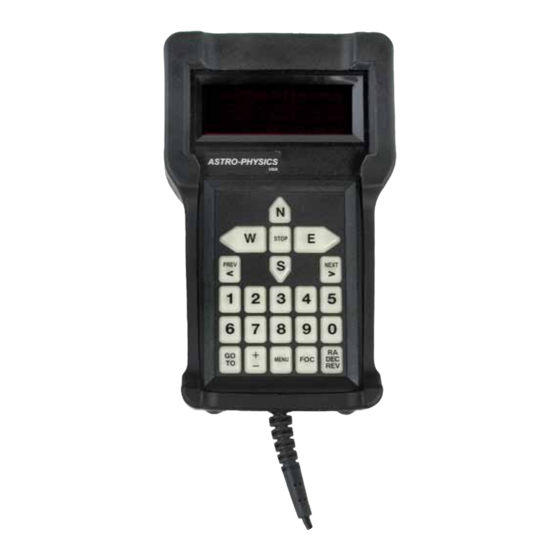
ASTRO-PHYSICS 1568GTO Manuale di istruzioni per la manutenzione - Pagina 12
Sfoglia online o scarica il pdf Manuale di istruzioni per la manutenzione per Tastiera ASTRO-PHYSICS 1568GTO. ASTRO-PHYSICS 1568GTO 17.

RePlaCing YouR gto KeYPad batteRY
(keypads 1568GTO and later)
see identifying Your Keypad battery in previous section.
Warranty considerations: the manufacturer warrants the astro-Physics gto Keypad for three years. if your keypad is
still within the warranty period, you may void the warranty by opening the keypad to make this repair.
tools and parts needed:
●
Phillips screwdriver, size #0
●
small flat blade screwdriver
●
Keypad with Keypad Protector removed (partially removed is oK - see KeYPRo
instructions)
●
new battery: aP # e0334 (cR2430 with 2.5" soldered pigtail) - must be purchased from
astro-Physics!
additional helpful documents in Previous sections:
●
Removing and installing the KeYPRo Keypad Protector
●
opening and closing the Keypad
●
identifying Your Keypad battery
●
Keypad database corruption and Reloading - html or Pdf
Please review the following instructions thoroughly. If you are not comfortable with the procedure, please
consider sending the keypad in to Astro-Physics for service. Your keypad should be UN-plugged for this
Remove the battery
1. Remove the KeYPRo, silicone-rubber keypad protector, following
the instructions in a previous document. the KeYPRo does not
need to be removed completely.
2. lay the keypad face down on your work surface. locate the
six small screws in the corners. undo these screws using a #0
Phillips screwdriver. be careful not to strip the screw heads. the
screws do not need to be removed completely. Just back them
out until you feel that they are no longer engaged.
3. carefully open the keypad, taking care to make sure that the white plastic
spacer-washers on the screws are not lost. these spacers are vital to
maintain separation of components and to protect the case from damage.
lay both halves of the keypad with the wires still connected flat on your
work space.
be extremely careful of the fiber-optic cable bundles throughout this
procedure! they are easily damaged. do not crush or sharply bend
the fibers!
4. unplug the display's ribbon connector as shown. gently work the connec-
tor off of the display header. be very careful not to damage the connector
or the pins of the display header that are on the main circuit board.
note: the connector will be snug. do not pull on connector carelessly. the display header pins may bend.
5. view of display connector unplugged (above right). at this point, the display can be carefully removed from the keypad.
lay the display aside on a soft surface. be very careful not to scratch the glass on the front of the display.
6. unplug the lithium battery connector. note the Real time clock (Rtc) module. this is not the battery!! do not at-
tempt to remove this! (see photo top of following page)
procedure!
11
