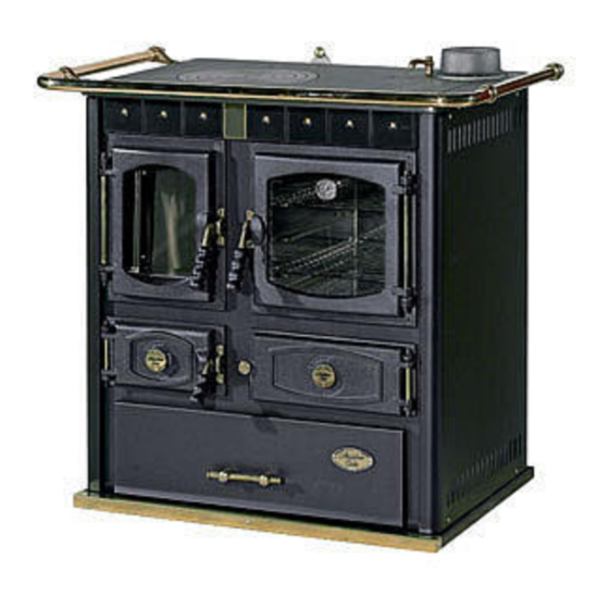
Cola MINI JOHANNA Manuale di installazione, uso e manutenzione - Pagina 8
Sfoglia online o scarica il pdf Manuale di installazione, uso e manutenzione per Stufa Cola MINI JOHANNA. Cola MINI JOHANNA 15.

2.3 Connection to the flue
The MINI JOHANNA stove must be connected to the flue by means of the collar on the hotplate, using flue pipes that
are readily available on the market. Connection to the flue must be made using strong and stable pipes (recommended
min. thickness 1.2-2 mm). The flue pipe must possibly be straight, to avoid pressure losses, and towards the flue. The
ends of the flue pipe must be tight.
To ensure regular operation, the flue draught with stove operating must be between 10 and 14 Pa.
For optimum stove efficiency, a draught control or damper must be fitted in the flue pipe or chimney.
Every unit must eliminate the fumes through its own flue; never use the same flue for several units.
2.4 Room ventilation
The air necessary for combustion, i.e. up to 25 m³ every hour, must be ensured in rooms where stoves with natural flue
draught are installed. The air change must occur through several fixed openings to the outside, whose cross section
must comply with the current local regulations. Such openings must be protected with grilles and must never be
obstructed.
If the air is insufficient, even the operation of an extractor hood in the room or exhaust fans can negatively affect stove
operation.
2.5 Advice on flues and connections
Flues must be made from suitable materials and perfectly insulated, with characteristics that prevent temperature
decreases.
The inner walls must be perfectly smooth without any narrowing or protrusions along the entire length, so as not to
create friction or vortices in the smoke which could cause a considerable reduction in draught.
Any cleaning and inspection doors must be perfectly closed during operation.
The flue outlets must be 0.5 m higher than any obstacles located less than 10 m away and must end with chimney
caps or cowls having a useful outlet cross section of at least double that of the flue.
The following two figures give the data regarding the distances and positioning of chimney caps in conformity with the
provisions of UNI 10683/98.
Approx. 0.5m
Min 0.5m
obstacle
Less than 5 m
UNI 10683/98 tables
Roof
(α)
(α)
(α)
(α)
slope
15°
30°
45°
60°
Min 0.5m
The chimney mouth must be at least
0.5m from the top of any obstacle
within a range of 10
Distance A
1.00 m
1.30 m
More than 1.85 m
2.00 m
2.60 m
m
fig. 3 Chimney cap positioning and distances
Roof slope
H
15°
30°
45°
60°
7
(α)
(α)
(α)
(α)
Distance B
Less than 1.85 m
H
0.50 m
0.50 m
0.50 m
0.50 m
Mini Johanna
