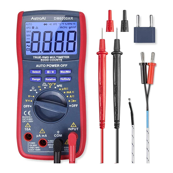
AstroAI WH5000A Manuale d'uso - Pagina 13
Sfoglia online o scarica il pdf Manuale d'uso per Multimetro AstroAI WH5000A. AstroAI WH5000A 16.

Diode Test
1. Connect the black test lead to the "COM" jack and the red test lead to the "INPUT " jack.
2. Set the function switch to "
3. Press the "Select" Button to select continuity measurement mode, and the symbol "
will appear on the display.
4. Connect the red test lead to the anode of the diode to be tested and the black test lead
to the cathode.
5. The meter will show the approximate forward voltage of the diode. If the connections are
reversed, "OL" will be shown on the display.
a. In this case, simply switch the test leads from the anode to the cathode and vice
versa.
Transistor Test
1. Set the function switch to"hFE "range.
2. Connect the multi-function socket to the "COM" and "INPUT" Jacks. The negative side of
the socket must meet COM and the positive to INPUT. It is very important not to reverse
these by mistake.
3. Identify whether the transistor is NPN or PNP type and locate Emitter, Base and
Collector lead. Insert the leads of the transistor to be tested into the proper holes of the
transistor test socket of the adapter.
4. Read the LCD display for the approximate hFE value.
Temperature Measurement
1. Set the function switch to "ºC/ºF" range.
2. Use the Select Button to choose either Celsius or Fahrenheit.
3.
Insert the negative (black) plug of the K-type thermocouple to the COM Jack and the
positive (red) plug to the INPUT Jack.
4. Carefully touch the end of the thermocouple to the object being measured.
5. Wait for the temperature reading to settle, then record the result from the LCD display.
Capacitance Measurement
1.
Set the function switch to "
2. Connect the multi-function socket to the "COM" and "INPUT" Jacks. The negative side of
the socket must meet COM and the positive to INPUT. It is very important not to reverse
these by mistake.
3. Place the capacitor into the multifunction-socket with the positive end in the positive
(INPUT) side of the multifunction-socket and the negative end of the capacitor in the
negative (COM) terminal of the multifunction-socket.
4. The results will be displayed on the LCD display.
5. If your Capacitor's legs are too short to be used with the multifunction-socket, use the
test leads:
a. Connect the black test lead to the "COM" jack and the red test lead to the "INPUT"
jack.
" range.
" range.
"
