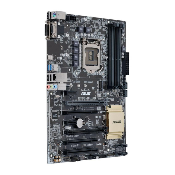
Asus B150M-PLUS Manuale tecnico - Pagina 6
Sfoglia online o scarica il pdf Manuale tecnico per Scheda madre Asus B150M-PLUS. Asus B150M-PLUS 18. Pin definition

3
Internal Connectors
1.
Serial port connector (10-1 pin COM)
This connector is for a serial (COM) port. Connect the serial port
module cable to this connector, then install the module to a slot
opening at the back of the system chassis.
2.
CPU and chassis fan connectors (4-pin CPU_FAN, 4-pin CHA_FAN)
Connect the fan cable to the fan connector on the motherboard,
ensuring that the black wire of the cable matches the ground pin
of the connector
Do not forget to connect the fan cables to the fan connectors.
Insufficient air flow inside the system may damage the
motherboard components. These are not jumpers! Do not place
jumper caps on the fan connectors! The CPU_FAN connector
supports a CPU fan of maximum 1A (12 W) fan power.
3.
USB 3.0 connector (20-1 pin)
This connector allows you to connect a USB 3.0 module for
additional USB 3.0 front or rear panel ports. With an installed USB
3.0 module, you can enjoy all the benefits of USB 3.0 including
faster data transfer speeds of up to 5 Gbps, faster charging time
for USB-chargeable devices, optimized power efficiency, and
backward compatibility with USB 2.0.
4.
USB 2.0 connector (10-1 pin)
This connector is for USB 2.0 ports. Connect the USB module cable
to this connector, then install the module to a slot opening at the back
of the system chassis. This USB connector complies with USB 2.0
specifications and supports up to 480Mbps connection speed.
1-6
COM
PIN 1
CPU_FAN
CHA_FAN
C
USB3
PIN 1
USB
PIN 1
Motherboard Pin Definition
