Cansec MAP2 Manuale di installazione - Pagina 4
Sfoglia online o scarica il pdf Manuale di installazione per Controllore Cansec MAP2. Cansec MAP2 16. Elevator control

Overview
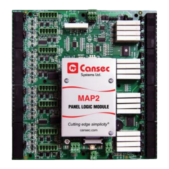
The MAP2 elevator control panel and the H1000 panel are designed to interface with the elevator
electronics using the "Form C" relay output contacts of the panels. These relay output contacts make
or break the connection to individual elevator floor buttons. The connection to these buttons is
provided by the elevator company.
The Wiegand Reader (located in the elevator cab) requires 6 conductors which will be connected to the
elevator travel cable used by the elevator. The elevator travel cable terminates in the elevator control
room, and from this location the 6 reader wires will be used to connect to the reader port of the MAP2
Elevator control panel.
Travel Cable
6 conductors
Wiegand Reader
The "Form C" relay output contacts of the MAP2 and H1000 panels are designed to switch only low
voltage. An Elevator Relay Interface Box is required to make the actual connection to the floor buttons
in the elevator electronics. The Elevator Relay Interface Box must be supplied by the elevator
contractor. 12 volt relays are to be used in the interface box. The MAP2 and H1000 panels' output
relay contacts will switch the 12 volt coil of the relay in the interface box.
Under no circumstance is 110/120 or higher voltage to be present in the access control panel (many
elevators use 110Volts AC or DC in the floor button circuitry which is considered a lethal voltage). A
service bypass switch must be installed in the Elevator Relay Interface Box to allow for fire alarm release
of all the floors in the event of a fire alarm and to allow service of either the access control system or
the physical elevator. If a bypass switch is not installed, both technical parties need to be present during
service of either the access control system or the elevator, and that can be quite costly.
Requirements
Wiegand reader mounted inside the elevator cab.
Elevator Relay Interface Box, supplied by elevator contractor.
MAP2 and optional H1000 controllers mounted in the elevator control room.
Refer to reader manufacturer for reader wire specifications.
MAP2 and H1000 relays should be used to switch low DC voltage, e.g. 12VDC.
Optional H1000 V1.1 controller and daughter card EX100 V1.1.
6 conductors
Elevator Cab
MAP2 Elevator Control
Installation Guide
MAP2 Elevator Control Panel
April 2020 • Rev. 1.0
Page 4 of 16
