Dormakaba 5750-K Manuali di installazione - Pagina 6
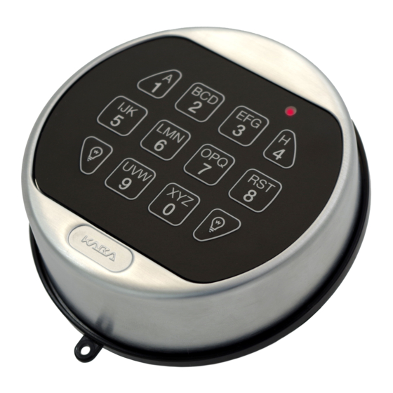
Sfoglia online o scarica il pdf Manuali di installazione per Sistema interfonico Dormakaba 5750-K. Dormakaba 5750-K 9. Electronic entry device
Anche per Dormakaba 5750-K: Istruzioni per l'uso dell'utente (2 pagine), Istruzioni per l'uso dell'utente (2 pagine)
dormakaba
LARGE BATTERY AND BATTERY/ALARM BOX:
1. Open safe door.
2. Remove battery box cover by pulling the front portion away from the safe door.
3. Insert six new "C" cell alkaline batteries
4. Replace the cover and test the lock several times before closing the door.
Figure 5 – 5750/5750-K battery door clearance required
>5 cm
NOTE: The 5750 and 5750-K Entry Device has the option of a permanently attached hinged battery door or a removable
battery door. The installer must decide which option to use before STEP 6 below. To allow full operation of the
permanently attached hinged battery door, there should be at least 5 cm of clearance from any object on the safe, such
as a knob or handle, directly beneath the bottom edge of the dial plate. See Figure 5.
SWING BOLT
1. Mount the dial plate (p/n 3752) centered on the through hole. Attach the dial plate with the two mounting screws US
8-32 (US) or the M4-0.7 (metric).
2. Slide the bearing plate (p/n 2674) over cable and press onto the fasteners on the Entry Device (Figure 6).
3. Feed the key pad cable through the spindle cable hole from the front of the safe door.
4. Insert the two springs (p/n 2893) and blocking pins (p/n 2894) into the holes located on the back of the keypad (Figure 7).
5. .Skip this step if the battery door is to be removable. Otherwise, attach the battery door to the keypad, by first inserting
the hinge pin into the hole on the battery door and then insert the battery door with hinge pin into the hinge pin hole on
the keypad housing (adjacent to the locking pin hole). See Figure 7.
WARNING: If the battery door is to stay permanently attached, the hinge pin must be inserted before the keypad is
secured to the dial plate (step 6). Once the keypad is fully installed, the hinge pin cannot be added or removed from the
safe door without the possibility of physical damage to the Entry Device or Dial Plate or both.
6. Rotate the keypad approximately 300 counter-clockwise and guide the keypad bushings into the large openings on the
dial plate. Then, turn the keypad clockwise until the blocking pins click into place and the keypad can no longer rotate.
7. When installing the lock on the opposite side of the safe door, ensure that the keypad cable is routed through the channel
on the base of the lock. (Figure 8.)
Figure 8 - Swing Bolt lock installation.
(P/N) 762.128 Rev G 05/17 • © copyright 2009-2018
5750 AND 5750-K ENTRY DEVICE
Figure 6
Keypad Bushings
Optional
Hinge Pin
Figure 7 – Blocking Pin and optional Hinge Pin placement.
Bearing Plate
Optional Hinge Pin
5