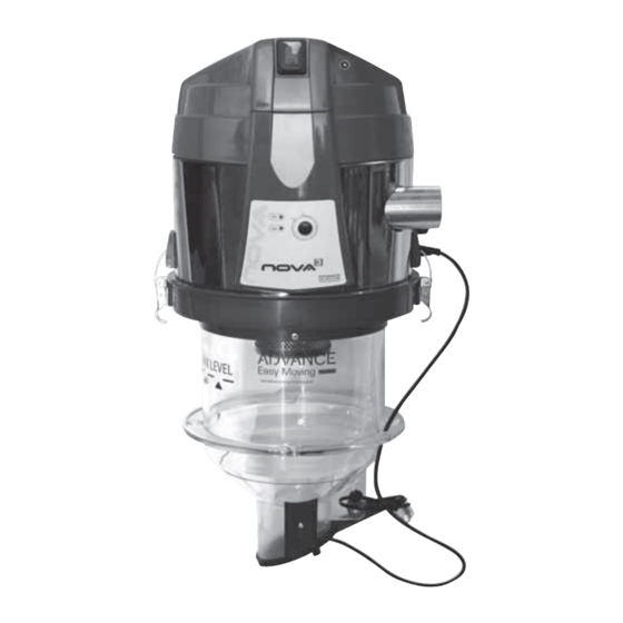
Advance acoustic AP1000.50.03 Manuale di montaggio, uso e manutenzione - Pagina 12
Sfoglia online o scarica il pdf Manuale di montaggio, uso e manutenzione per Aspirapolvere Advance acoustic AP1000.50.03. Advance acoustic AP1000.50.03 20.

Instruction manual for integrated vacuum unit
6.3 Connection to the piping network
Both the Ø 50 mm pipes of the vacuum unit must be connected with at least one piece of
antistatic fl exible hose with equal diameter, secured with well-fi xed hose clamps.
The other end of the antistatic pipe should be connected to the rest of the fuel transport system,
which can still be made with fl exible antistatic pipe or steel pipes, also present in the catalogue.
To avoid static currents, the copper strand in the antistatic pipe must always be in contact with
a grounding or other steel pipes belonging to the fuel transport system.
The OUT pipe exhausts dusty air from the central vacuum unit, while the IN pipe transports the
fuel to the unit dispenser.
The air exhaust pipe can be connected with a fuel extraction accessory where provided;
otherwise, it should be connected to the dust collectors present in the catalogue. The maximum
allowed gross length between the fuel withdrawal point and the central vacuum unit is 25 m.
The following elements affect the calculation of the net length of the pipe:
- the type of fuel to be conveyed
- the number of curves inserted in the section where the fuel passes
- the length of the vertical paths inserted in the section where the fuel passes
The maximum allowed length of the exhaust pipe (expulsion) of the air exiting the central unit
is 5 m (single-pipe system)
The maximum allowed length of the air expulsion pipe exiting the central unit, if it returns to the
fuel withdrawal point, is 10 m (double pipe system)
See "system technical data" on our website
6.4 Electrical Connection
Before making the electrical connection, check that the supply voltage corresponds to
the one required and that the electrical system to which the product is connected is
done in compliance with current regulations.
Connect the two wires of the activation line called AUX to the motorized extraction system (if
present).
Check that the two operation consent wires, labeled MICRO, are connected together.
Alternatively, the two wires called MICRO can be connected
- to the control system of the boiler if the latter is predisposed for this.
- to a timer in order to program the operating times
- to a remote automatic activation system
- to a level sensor (see our catalog)
Connect the power cable to a 230 V ac power outlet.
12
31/05/2021 Rev:1.04
